Instrument Flight
Aircraft Instrumentation
ATTITUDE DIRECTOR INDICATOR (ADI) DISPLAY
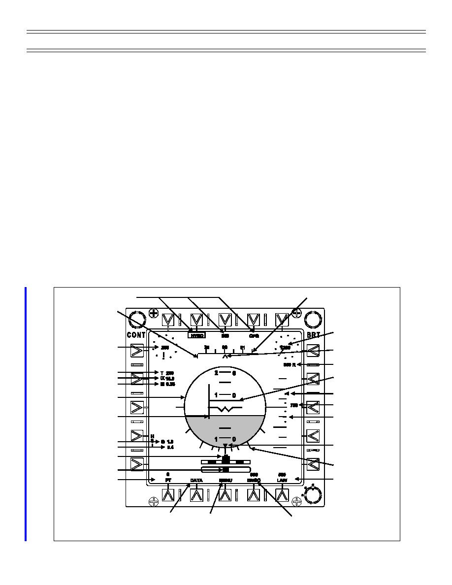
The ADI display is the primary control instrument. It replicates a conventional electromechanical ADI
instrument. It provides your primary indication for the aircraft’s attitude using the horizon bar, bank
pointer, pitch reference scale, and the attitude display. Whenever a deviation from a desired performance
is indicated on one of the performance instruments, the correction should be made referencing the ADI
display.
In addition to the typical ADI, the ADI display includes additional flight parameters (Figure 1). True
airspeed, AOA, Mach, g, and peak g are shown digitally on the left-hand side of the display. Indicated
airspeed and barometric altitude, trend indicators and a heading scale are across the top of the display.
The digital indicated airspeed has a resolution of one kt. The indicated airspeed trend indicator wiper
blade rotates clockwise for increasing airspeeds and counterclockwise for decreasing airspeed. The
airspeed trend scale is graduated in 10-kt increments with multiples of 100 kts at the 12 o’clock position.
The digital barometric altitude resolution is 20 ft. The barometric altitude trend indicator wiper blade
rotates clockwise for increasing altitude and counterclockwise for decreasing altitude. The altitude trend
scale is graduated in 100-ft increments with multiples of 1,000 ft at the 12 o’clock position. The heading
scale, with heading numbers and scale tick marks, scrolls left or right above a fixed caret. A command
heading bug, a vertical line, is referenced to the heading scale. The command heading is referenced to
the selected navigation aid unless ILS or no steering is selected. With ILS or no steering selected, the
command heading bug location is determined by the heading value set on the HSI display heading option.
A digital radar altitude and a vertical velocity trend indicator are to the right of the display. The vertical
velocity scale limits are -2,000 ft/min and 1,500 ft/min. Dashes are located at -2,000, -1,000 and
Position Data Source
Heading Scale
Command Heading
Bug
Barometric Altitude
Indicated Airspeed
Aircraft Heading
Reference
Radar Altitude
True Airspeed
ILS Glideslope
Angle of Attack
Needle
Mach
Vertical Velocity Caret
Attitude ball
Vertical Velocity
ILS Localizer Needle
Vertical Velocity
Scale
Normal Acceleration
Bank Angle Pointer
Peak G
Turn Indicator
Bank Angle Scale
Sideslip Indicator
Low Altitude Warning
ADI Pitch Trim Setting
D
N
Setting
OFF
Data Option
Menu Option
Bingo Fuel Setting
Figure 1: ATTITUDE DIRECTOR INDICATOR DISPLAY
Page 10
(4-01) Original


 Previous Page
