Instrument Flight
Aircraft Instrumentation
Law Entry Initiation Option
Pushbutton Barrier
ON
N
LAW
OFF
1
2
3
Mil Depression Entry For DSL Reticle
+
SET
(Option active when A/G Manual
AUTO
delivery mode selected)
W
E
DEP
CRS
-
4
5
6
DAY
Course Line Entry Initiation Option
Heading Bug Entry Initiation Option
-
S
+
BRT
HDG
7
8
9
MODE
Master Mode Selection Option
DCL
ENT
CLR
BNGO
0
HUD Declutter Level
Bingo Fuel Entry Initiation Option
Selection Option
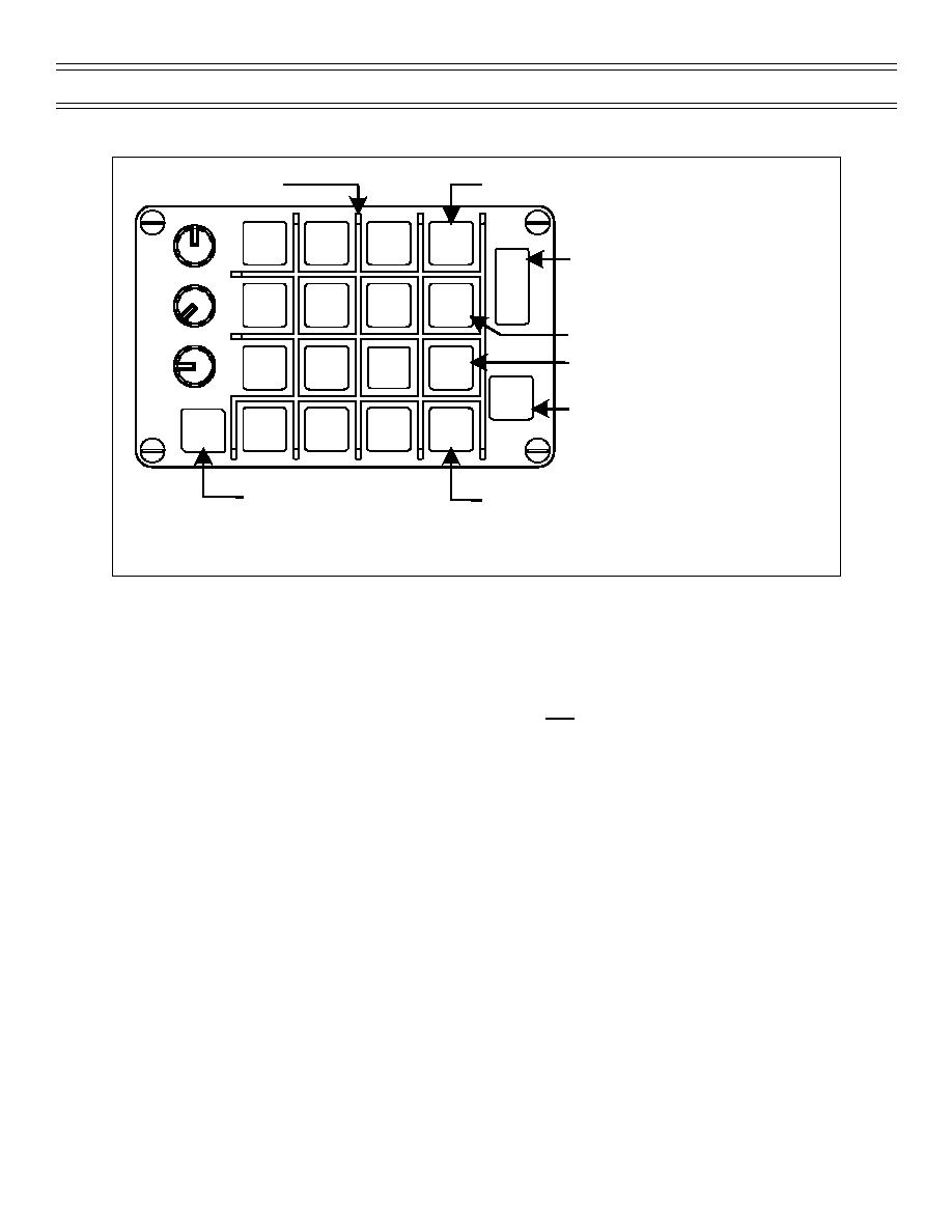
Figure 4: DATA ENTRY PANEL
pointer for the selected steering reference is displayed. In the Course Deviation Indicator (CDI) mode, the
inner bar represents deviation from the selected course. If TACAN or VOR is the selected steering, each
dot represents 5 degrees of course deviation. For waypoint or waypoint offset steering, the scale varies
based on landing gear position. With the landing gear up, full scale deflection of the inner CDI bar
represents a +/- 4.0-nm cross track deviation. With the landing gear down, a full scale deflection
represents a +/- 0.3-nm cross track deviation. When ILS is the only steering selected, the CDI deviation
scale is relative and must be interpreted by the pilot depending on the width of the localizer course. If the
localizer course is 5 degrees wide, a full scale deflection represents a 2.5-degree deviation. In addition to
the typical CDI course line, a planimetric (PLAN) course line can be selected. The planimetric course line
is only available for TACAN or Waypoint steering. The planimetric course line is drawn through the
selected steering symbol (TACAN, waypoint, or waypoint offset). Course intercept angle and deviation
are shown by the relationship of the planimetric course line to the aircraft symbol. The course line is only
shown when CRS is selected on the HSI display. The course is set with the increment and decrement
arrows on the HSI display or by selecting CRS on the HUD data entry panel and entering the course with
the number keys. The scale of the compass rose can be set to 10, 20, 40, 80, or 160 nautical miles.
TACAN, waypoint, and waypoint offset symbols are shown within the compass rose relative to their
bearing and distance from the aircraft symbol and the selected scale of the compass rose. Digital
bearing, slant range distance, and time-to-go are provided for waypoints and valid TACAN stations.
Digital bearing is also shown for a valid VOR station. A sequential steering string of two or more
waypoints can also be displayed as a dashed line on the HSI display. Navigation control selection is also
made on the HSI display indicating either FWD or AFT.
Page 13
(4-01) Original


 Previous Page
