Instrument Flight
Aircraft Instrumentation
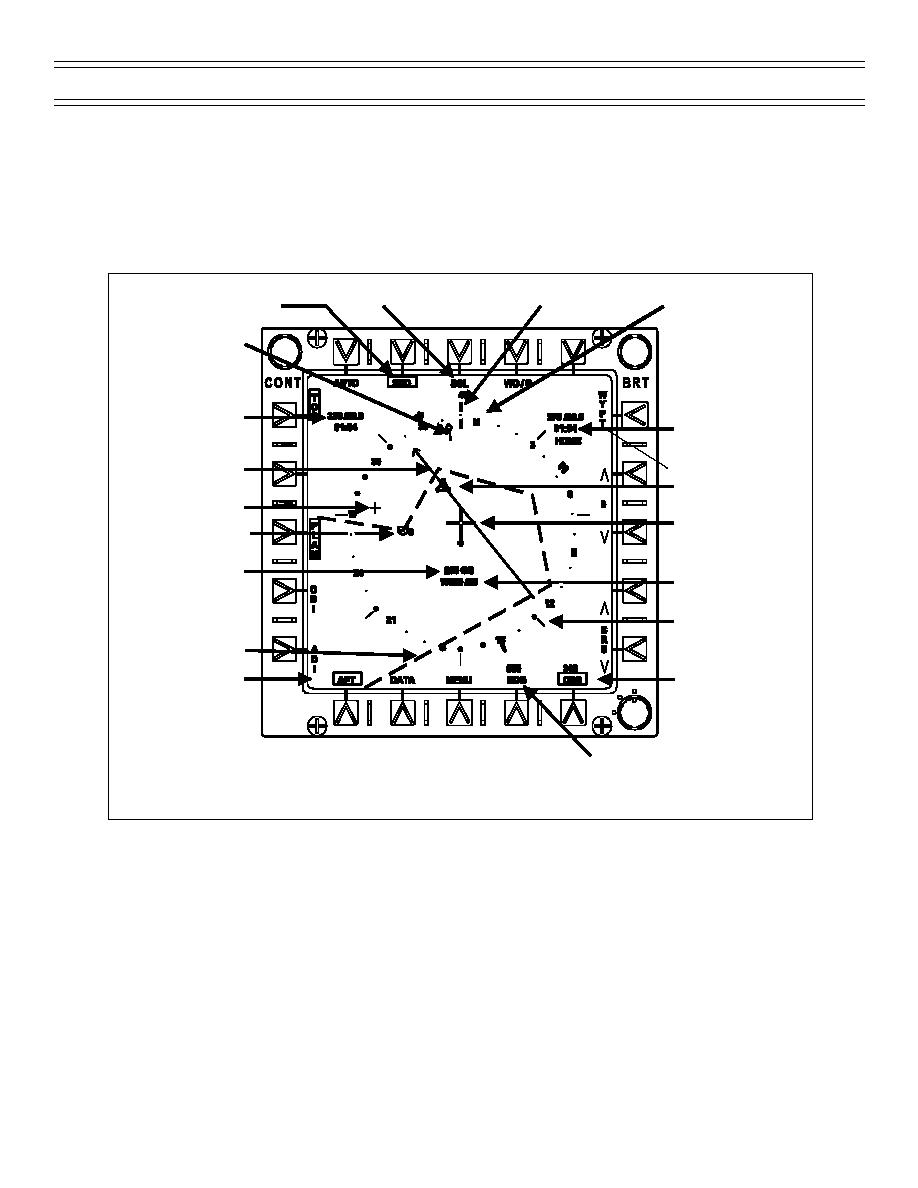
HORIZONTAL SITUATION INDICATOR (HSI) DISPLAY
The HSI display performs the course deviation indication function of a conventional electromechanical
instrument. With the capabilities of the Global Positioning/Inertial Navigation Assembly (GINA) and
display electronic unit (DEU), additional display options and navigation information are available on the
HSI display (Figure 3).
Compass Rose Scale Selection
Sequential Steering
Lubber Line
Compass Rose
String Selection
Ground Track Marker
TACAN Data Block
Waypoint / Offset
Data Block
Planimetric Course
Line
TACAN Symbol
Offset Symbol
Aircraft Symbol
Waypoint 0 Symbol
Ground Speed
Wind Direction /
Speed
Benchmarks
Sequential Steering
String
Course Line Setting
Navigation Control
D
and Selection
N
OFF
Heading Bug Setting
and Selection
Figure 3: HORIZONTAL SITUATION INDICATOR DISPLAY
The aircraft symbol is fixed in the center of the display, heading up. Ground speed, and wind direction
and speed are below the aircraft symbol. The compass rose rotates according to the aircraft magnetic
heading, referenced to a lubber line and the actual ground-track marker.
Reference benchmarks are spaced every 45 degrees around the periphery of the compass rose. A split
heading bug is located on the periphery of the compass rose. The heading bug is positioned according to
the heading set with the increment and decrement arrows on the HSI display or by selecting HDG on the
HUD data entry panel (DEP) (Figure 4) and entering the heading with the number keys. The head and tail
of the TACAN bearing pointer are located on the outer edge of the compass rose. The head and tail of the
VOR or waypoint bearing pointer are located on the inner edge of the compass rose. Only the bearing
Page 12
(4-01) Original


 Previous Page
