Instrument Flight
Aircraft Instrumentation
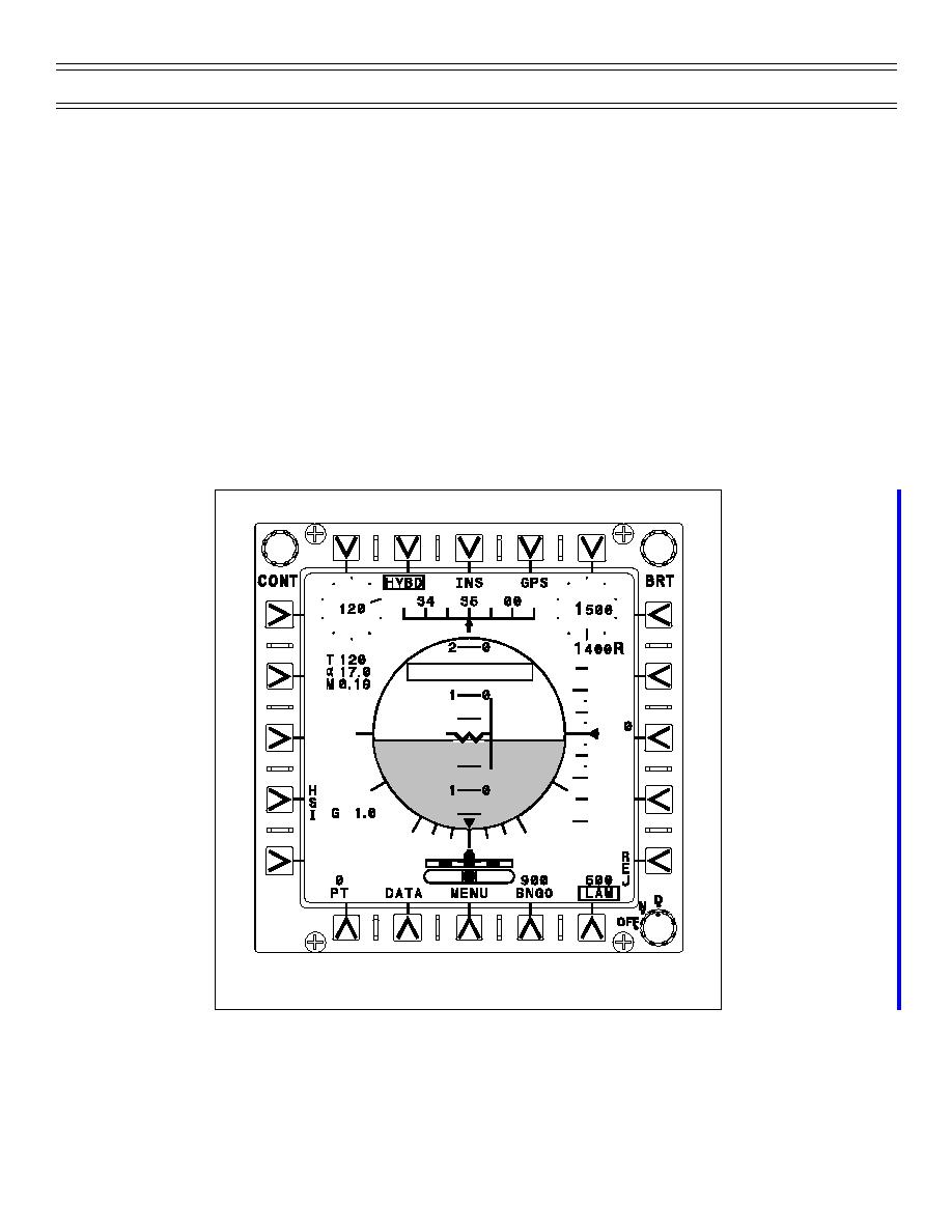
1,000 ft/min. Tics are located at -750, -250, 250, and 750 ft/min. The digital vertical velocity resolution is
10 ft/min. The vertical velocity caret is open when vertical velocity exceeds - 2000 or + 1600 ft/min. The
digital vertical velocity range is +/- 9,990 ft/min. A turn and slip indicator is at the bottom of the display.
The shaded reference areas to the left and right of the shaded center marker represent a +/- 3 degrees
per second turn rate (standard-rate turn). BNGO fuel and Low Altitude Warning (LAW) height settings are
also on the ADI display. The ADI display pitch can be adjusted +/- 5 degrees in relation to the waterline
with the “PT” selection. With a valid ILS channel station selected and ILS steering selected, ILS needles
are shown. The needles are referenced to the waterline. The localizer and glideslope needles range
+/- 1/2 inch from the waterline. Full deflection represents +/- 2.5 degrees of azimuth deviation (with a
5-degree localizer signal) and +/- 0.7 degrees of glideslope deviation. The localizer or glideslope needle
will flash when limited. The needles for an invalid input are removed and an MFD advisory window,
“GLIDESLOPE” (Figure 2), “LOCALIZER,” OR “ILS” will flash on all MFDs. The advisory window will
remain on the MFDs until either the REJ button is depressed or the failed data becomes valid again. The
ADI display is normally placed on the left MFD to facilitate cross-checking the standby instruments on the
left side of the main instrument panel.
G L ID E S L O P E
Figure 2: FAILED ILS GLIDESLOPE
Page 11
(4-01) Original


 Previous Page
