Flight Procedures
Instrument Flight
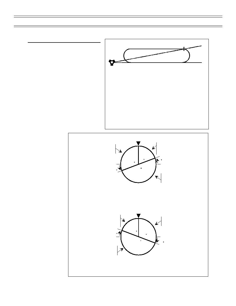
No-Wind VOR/TACAN DME Entry Offset
082
Prior to reaching the holding fix on a
30 DME
teardrop or direct entry, based on the
T-45C turn radius for 180 degrees at
holding airspeed, the pilot should calculate
090R
the approximate offset required so, at the
inbound turn point, an SRT or 30-degree
NO WIND
AOB turn for 180 degrees will place the
Offset 8 radials according to table:
aircraft on the holding course inbound.
The actual offset required will vary with
wind, true airspeed, altitude and turn
radius. For 200 KIAS at 15,000 ft, the
DME
RADIAL OFFSET
T-45C turn radius is approximately 2 nm,
(At turn inbound)
(Approximate)
or 4 nm for 180 degrees of turn. See
10
24
Figure 31.
20
12
30
8
The quickest and most accurate method of
40
6
determining which type of entry to perform
is to use the HSI display compass rose as
Figure 31: NO-WIND HOLDING OFFSET
a plotting board
(Figure 32). For a
standard holding
Heading Index
pattern, locate the
TEARDROP SECTOR
PARALLEL ENTRY SECTOR
holding radial on the
Turn in shortest direction to
Turn left to parallel the
heading 30 degrees less
compass rose. If the
outbound course
than the outbound course
holding radial is
located within an
70
20
110
area of 70 degrees
to the right of aircraft
20
180
heading at the
DIRECT ENTRY SECTOR
holding fix, perform
Turn right to the
a teardrop entry. If
outbound course
the holding radial is
STANDARD HOLDING PATTERN ENTRY
located within an
area of 110 degrees
to the left of aircraft
heading, perform a
parallel entry. If the
Heading Index
TEARDROP SECTOR
holding radial is
Turn in shortest direction to
PARALLEL ENTRY SECTOR
located outside an
heading 30 degrees more
Turn right to parallel the
area of 110 degrees
than the outbound course
outbound course
to the left and 70
70
degrees to the right
20
110
of aircraft heading,
20
perform a direct
180
DIRECT ENTRY SECTOR
entry. For a
Turn left to the
nonstandard pattern
outbound course
(left turns), reverse
the 70- and 110-
NONSTANDARD HOLDING PATTERN ENTRY
degree lines.
Additionally, most
Figure 32: DETERMINING HOLDING ENTRY
approach plates
include a holding entry diagram to aid you in determining which type of entry to perform.
Page 85
(4-01) Original


 Previous Page
