Flight Controls
T-45A UJPT, E2-C2, ADV, & IUT Eng-11
b.
Standby stabilator trim (STBY STAB
Sg 2, fr 8
TRIM) switch (guarded): located on
(1 Overlay)
each left console
c.
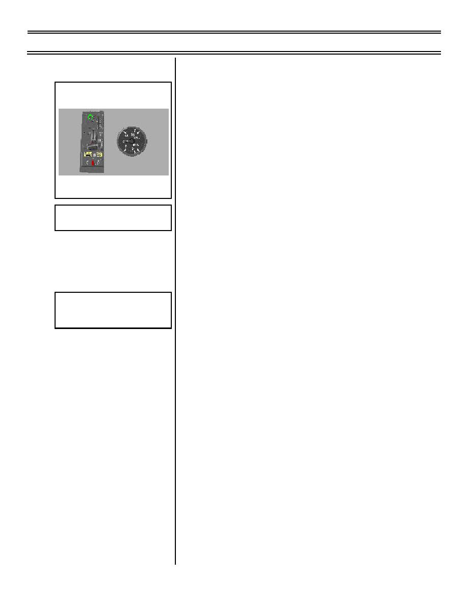
Stabilator position indicator: located
on left console, left of AILERON trim
indicator
NOTE: Stabilator position indicator is
STABILATOR CONTROLS/
just that, it shows current position of
INDICATORS
stabilator, not trim. As pilot pushes
and pulls on control stick, the stabilator
Overlay 1
position indicator moves to show
Stabilator Position Indicator
current position of stabilator. Hands
off control stick - aerodynamic forces
will move stabilator and control stick,
then stabilator position indicator will
show where stabilator is trimmed.
3.
Operating characteristics/limitations
Sg 2, fr 9
Stabilator System Components--
a.
Stabilator powered by tandem
Simplified
hydraulic actuator: failure of either
hydraulic system will not affect
operation
b.
Stabilator trim actuator consists of
main and standby motor
(1) Main motor powered by 28 VDC
essential bus. Operated by trim
switch on control stick
(2) Standby motor powered by 28
VDC generator bus. Used in case
of main motor failure. Controlled
by STBY STAB TRIM switch
NOTE: Both motors are
deenergized by travel limit
switches. Lifting the STBY STAB
TRIM switch guard disables the
main trim motor and allows use of
the standby trim switch.
Page 11-10
(8-03) Original


 Previous Page
