Flight Controls
T-45A UJPT, E2-C2, ADV, & IUT Eng-11
(b) Provide mechanical power to
Overlay 3
move ailerons
c.
Aileron trim actuator
(1) Location: aft of aft cockpit floor,
right of aircraft centerline
AILERON TRIM ACTUATOR
(2) Function: provides power to trim
aileron control surfaces
d.
Aileron spring feel unit
Overlay 4
Aileron Spring Feel Unit
(1) Location: just forward of trim
actuators
(2) Function: provides pilot with
artificial "feel" of aerodynamic
forces acting on control surfaces
(trimming relocates neutral
position of artificial feel unit)
2.
Cockpit controls/switches/indicators
a.
Aileron/stabilator trim switch
Sg 2, fr 3
Aileron/Stabilator Trim Switch
(1) Location: top of control sticks
(2) Function: five-position switch
which provides for four-way trim
b.
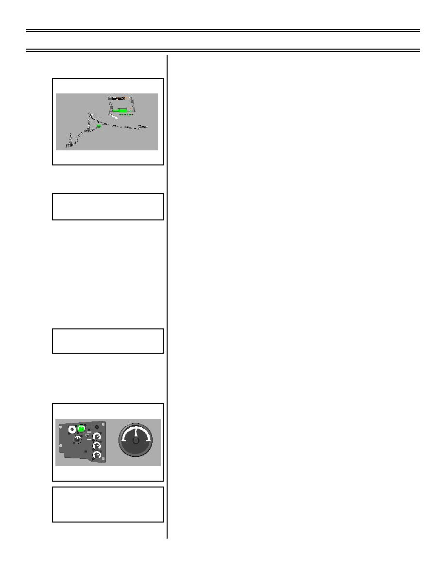
AILERON trim indicator (each cockpit)
Sg 2, fr 4
(1) Location: left console, forward of
10 15
TAIL
5
PLN
AILERON
0
5
H
throttle quadrant
Y
2
1
3
D
0
4
RESET 2
PSI
X
1000
RUDDER
H
Y
2
1
3
D
AILERON
1
0
4
PSI
X
1000
B
R
2
A
1
3
(2) Function: shows relative position
K
0
4
PSI
E
X
1000
of aileron trim
AILERON TRIM INDICATOR
3.
Operating characteristics/limitations
Sg 2, fr 5
Aileron System Components--
a.
Each aileron is powered by tandem
Simplified
hydraulic actuator (PCU)
Page 11-6
(8-03) Original


 Previous Page
