T-45A UJPT, E2-C2, ADV, & IUT Eng-09
Hydraulic System
(2) HYD 1 and HYD 2 PRESS and
RAT EXTEND caution lights
2.
Aircraft exterior indicators
a.
Accumulator pressure gauges: HYD 1
FC; HYD 2 FC; wheel brake/
emergency flap
b.
HYD 1 and HYD 2 reservoir quantity
indicators
c.
HYD 1 and HYD 2 filter indicators
NOTE: Each of these systems will be discussed in
detail.
LECTURE NOTES
Use the T-45A cockpit and aircraft cutaway view wall
charts to identify controls, indicators, and components
during this lesson. Emphasize component functional
descriptions.
II.
Hydraulic system no. 1 (HYD 1) 1.4.8.3.1
Sg 2, fr 1
Lesson Organization
A.
Description:
Sg 2, fr 2 (7 Overlays)
The HYD 1 reservoir supplies fluid to the HYD 1
engine-driven pump (EDP) that, in turn,
WARNING
CAUTION
HYDFAIL
RATEXTEND LIGHT
LIGHT
CAUTION
CAUTION
HYD1PRESS LIGHT
HYD2PRESS
LIGHT
MICRO
SWITCH
RAT
RESERVOIR
RESERVOIR
produces hydraulic pressure to power the flight
FCACCUM
FCACCUM
EDP
EDP
controls and general services.
LAIL
PRIORITY
VALVE
RAIL
HAND
PUMP
STAB
NOTE: Control of the rudder is strictly
SLATS
LGEAR
NWS
SPDBRK
FLAPS
LBAR
mechanical.
HOOK
HYD1PRESSURE
MECHANICAL
HYD2PRESSURE
WHLBRKS
CHECKVALVE
PRESSURIZEDWITH
FLAPEMERGENCY
RATEXTENDED
SELECTOR/PRIORITY
ANDGATE
VALVE
ELECTRICAL
B.
HYD 1 components
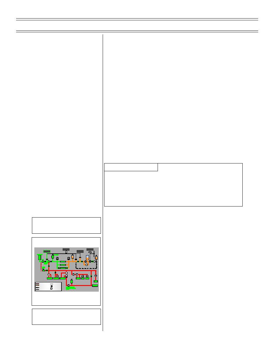
HYDRAULIC SYSTEM BLOCK
DIAGRAM
1.
Reservoir
Overlay 1
HYD 1 Reservoir
a.
Location: ram air turbine (RAT) bay,
top side of aircraft, forward of the tail
section (vertical stabilizer)
(8-03) Original
Page 9-4


 Previous Page
