T-45A UJPT, E2-C2, ADV, & IUT Eng-26
Engineering Review
9.
ROTATION advisory light: indicates N1
shaft rotating in correct direction at 100 rpm
or greater, engine igniters energized. Goes
out at 45% engine rpm, igniters
deenergized
D.
Engine starting system: engine is started (on
Sg 1, fr 4
ground or by assisted relight in flight) by gas
turbine starter (GTS) and air turbine starter
1.
Starting system components function
a.
Gas turbine starter: annular reverse-
flow gas turbine air-producer unit
which supplies starting air to motor the
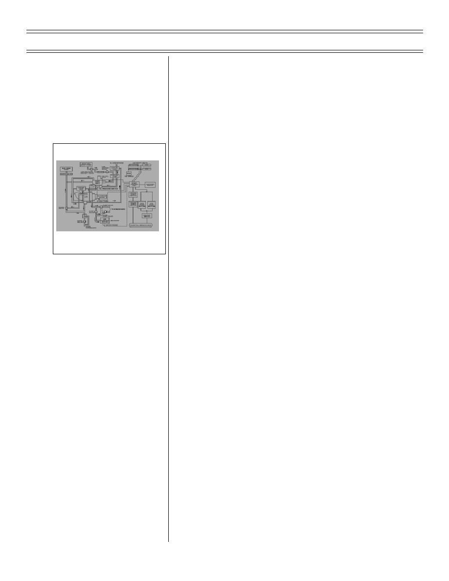
ENGINE STARTING SYSTEM
air turbine starter (ATS)
BLOCK DIAGRAM
b.
Air turbine starter: output shaft drives
engine N2 shaft through external
c.
Start control unit: sequences start
cycle by monitoring speeds of GTS, air
turbine starter, and engine
NOTE: SIFCU controls fuel during
start; after start, engine fuel is
controlled by ECA and throttle
movement
2.
Engine starting component function
a.
Bleed air valve: relieves pressure from
b.
Igniters: two high-energy, 12-joule
igniter plugs fitted to engine
combustion chamber are supplied by
28 VDC essential services bus
(8-03) Original
Page 26-12


 Previous Page
