T-45A UJPT, E2-C2, ADV, & IUT Eng-26
Engineering Review
Sg 1, fr 1
PRESENTATION
Lesson Organization
I.
Engine system
A.
Engine
1.
Air intake and compression
Sg 1, fr 2
a.
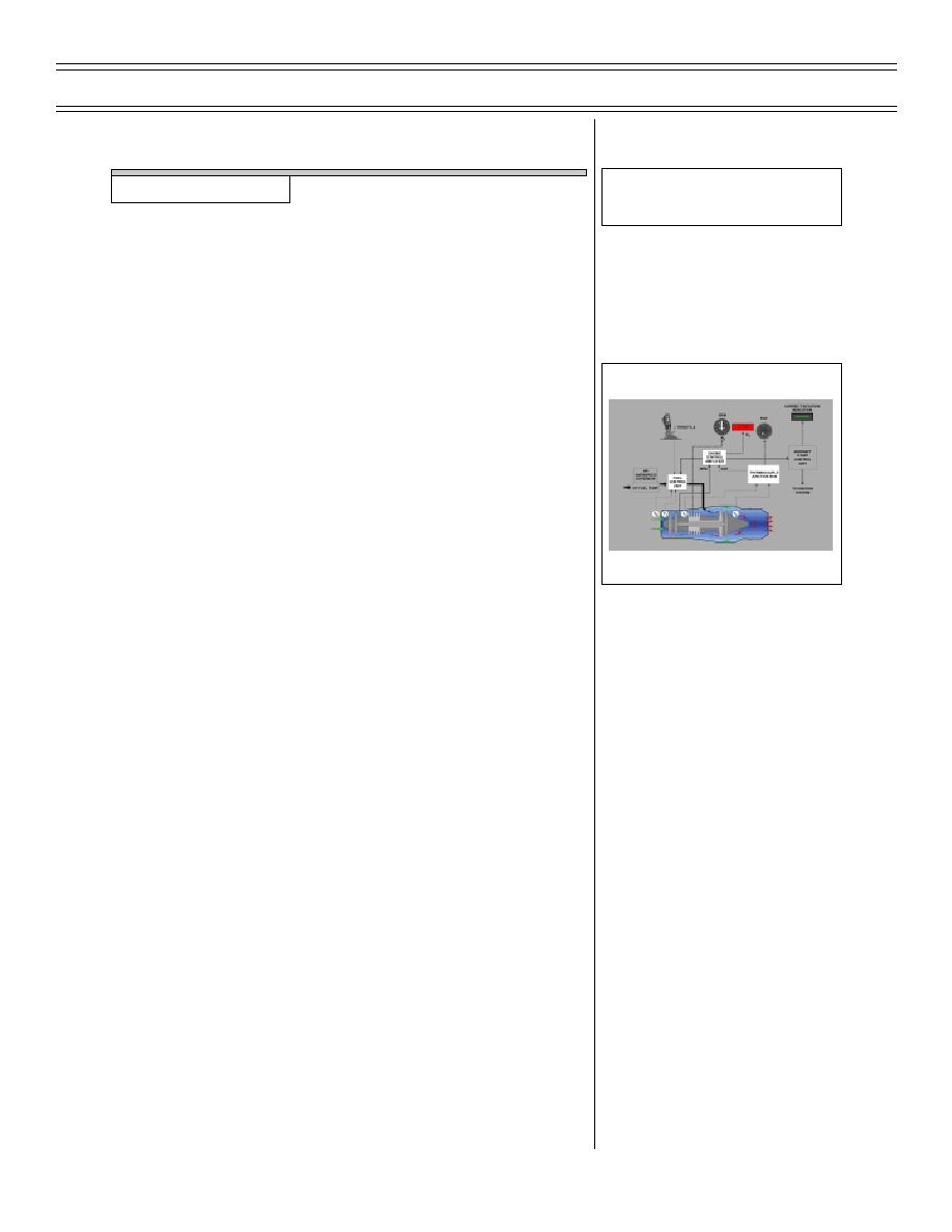
Air intake and compression: two inlet
ducts route air to N1, a two-stage low-
pressure compressor
b.
Compressed air from N1 then routed to
bypass duct
BASIC ENGINE BLOCK DIAGRAM
2.
Combustion
a.
Fuel is introduced through 18 fuel
spray nozzles and mixed with N2
compressed air in annular combustion
chamber
b.
Two high-energy 12-joule igniter plugs
ignite fuel/N2 air mixture. Mixture
expands, forcing high-pressure gases
into turbine section
3.
Power generation
a.
N2 and N1 turbines extract energy from
gases exiting combustion chamber to
drive their respective compressors
through coaxial shafts
b.
Internal gearbox extracts mechanical
energy from N2 shaft, providing power
to external gearbox
c.
External gearbox mechanically drives
aircraft accessories, e.g., generator,
hydraulic pumps, and fuel pumps
Page 26-9
(8-03) Original


 Previous Page
