T-45A UJPT, E2-C2, ADV, & IUT Eng-26
Engineering Review
B.
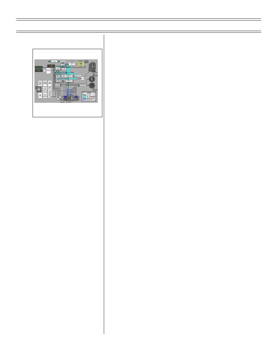
Engine fuel system
Sg 1, fr 3
1.
Automatic (NORMAL) controls override
mechanical controls, preventing engine
from exceeding operating limits (FUEL
CONTRL switch set to NORMAL)
2.
Fuel transferred to engine LP fuel pump
from aircraft fuel system
ENGINE FUEL SYSTEM
BLOCK DIAGRAM
3.
LP fuel pump: mounted on and driven by
external gearbox; maintains fuel pressure
to HP fuel pump, preventing HP fuel pump
4.
HP fuel pump: mounted on and driven by
external gearbox; supplies HP fuel to fuel
control unit (FCU) and sub-idle fuel control
unit (SIFCU)
5.
Engine control amplifier (ECA): trims fuel
flow in response to T6 temp (EGT) and N1
speed
C.
Monitoring and indicating
1.
Fuel flow indicator: operating limitations
a.
Idle: 300-400 pph
b.
Maximum: 6,410 pph
2.
EGT indicator: indicates exhaust gas
temperature
a.
Normal (maximum continuous):
550 degrees C
b.
MRT (30 min/flight hour):
610 degrees C
c.
Transient/acceleration (less than
20 seconds): 645 degrees C
Page 26-10
(8-03) Original


 Previous Page
