Landing Procedures
Familiarization
90 degrees
450 ft AGL
45 degrees
325 to 375 ft AGL
180 degrees
Start
600 ft AGL
15 to 18 seconds
Abeam
Approx. 1 nm
600 ft AGL
Establish Downwind
Touch & Go/Waveoff
600 ft AGL
130 KIAS
30 AOB
Wind Direction
Normal Pattern
PRINT
Pattern with No Wind
Correction
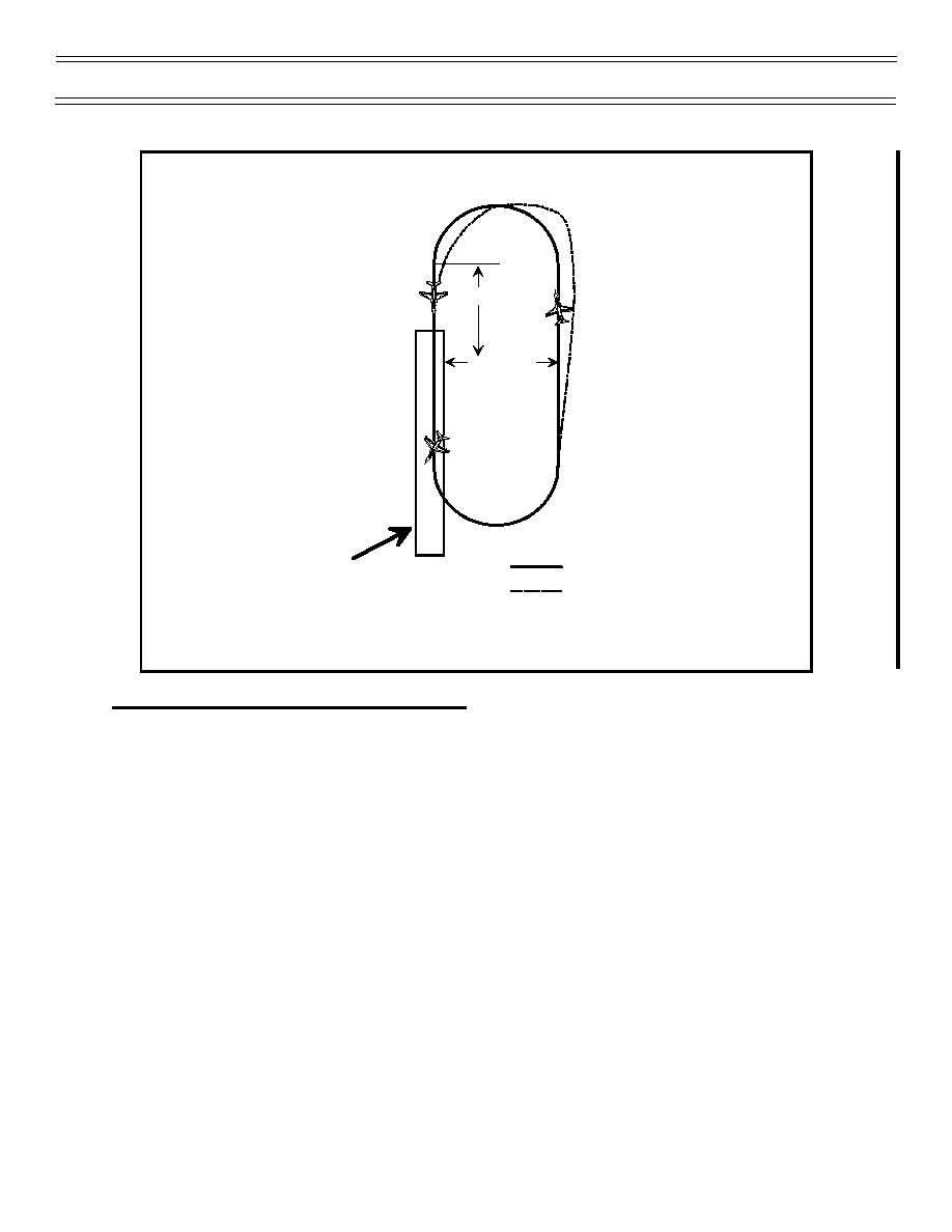
Figure 21: PATTERN CORRECTIONS, UNDERSHOOTING WINDS
TRACKING THE GLIDESLOPE—CORRECTIONS
FRESNEL LENS
The glideslope is projected by the Fresnel lens, an electro-optical landing aid that provides a visual
reference of optimum glideslope to pilots on approach to landing. It consists of a lens assembly, “cut”
lights, waveoff lights, and datum lights.
The lens assembly is a box 1 foot wide by 4 feet high that contains 5 vertical light cells, called “source
lights.” Depending on your position in relation to the glideslope, 1 of the 5 cells will be illuminated (upper
4—amber, bottom—red). Cut lights (four green lights mounted horizontally and centered above the lens
box) are used during NORDO conditions at the ship to signify “roger, ball” and that power must be added.
The red waveoff lights, mounted vertically on each side of the lens box, indicate the LSO’s mandatory
command to wave off the approach immediately. In addition, some waveoff lights are controlled by the
tower. The green datum lights, horizontally aligned on either side of the lens box, indicate a datum for
a centered ball. Figure 22 presents the indications you can expect to encounter while tracking
the glideslope.
Page 51
(1-00) Original


 Previous Page
