 |
|||
|
|
|||
|
|
|||
| ||||||||||
|
|  STUDENT GUIDE
VISUAL NAVIGATION
level routes such as VR-1006, VR151, VR-1632 or VR1040, use either the departure field or
destination field, whichever is closer. Using the distance measured, enter the Bingo Table and
interpolate as necessary for bingo fuel and distance. Measure and record the heading, applying
magnetic variation. Format for bingo information is Fuel, Magnetic course, and Altitude.
6.5.12. Plotting Class B and C Airspace
6.5.12.1. Plot Class B and C airspace exactly as was done for T-34 VNAV charts. Refer to VFR
sectional charts and low enroute charts located at Griffith Hall. Annotations for divert fields
remain the same: a 5 NM square for military, and a 5 NM triangle for emergency diverts.
However, 6000 feet of hard surface runway is required for all T-1 diverts, and 5000 feet for T-39
diverts.
6.5.13. Plotting Special Use Airspace (MOA, Restricted, Prohibited, and Warning areas)
6.5.13.1. Refer to the VFR sectionals and AP-1/A to determine what special use airspace falls
within 20 NM of the low-level route. While these airspace boundaries are commonly printed on
TPC charts, they are frequently incorrect and do not indicate altitudes or operating hours, while
CHUM products do not identify these errors. Using the VFR Sectionals, low charts and AP-1/A,
obtain the following information for each special use airspace within 20nm of the low-level
route:
6.5.13.1.1. Correct boundaries
6.5.13.1.2. Altitude structure
6.5.13.1.3. Operating hours
6.5.13.1.4. Controlling Authority
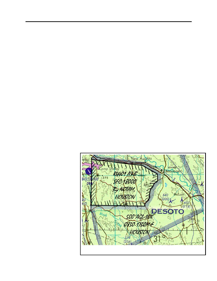
6.5.13.2. Annotate the
boundaries on your chart with
hatched black lines, as
illustrated in figure 6-11.
6.5.13.3. Note how R4401
A&B is not depicted on the
original TPC H-24B. By
referencing the VFR Sectional
for New Orleans and AP-1/A
the area, altitudes, times, and
controlling stations are
determined. The Desoto 1
MOA is also identified and
annotated, but as the printed
boundaries are correct, there is
no need to redraw them.
Information for MOAs also
may be found in the Low
Enroute Charts, VFR
sectionals or AP-1/A.
Figure 6-11
6-14
|
|
Privacy Statement - Press Release - Copyright Information. - Contact Us |
