T-45C TS & ADV CO-09; IUT CO-05
Velocity Vector
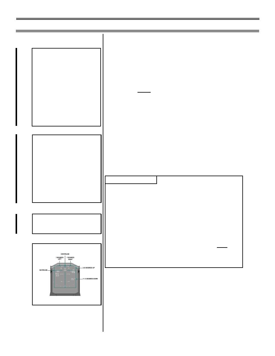
III. Display limits 1.9.3.1.5
Sg 3, fr 1
HUD VELOCITY VECTOR
A. Unlimited velocity vector movement
PROCEDURES
1.
Definition of UNLIMITED: When the
* Aircraft Movement Versus
Heading
velocity vector is displayed at some point
* Velocity Vector Relationship
within the HUD display limits; not flashing
to Aircraft Waterline
at the edge
* Display Limits
* Uncaged and Caged
2.
Vertical (from the waterline): 11.13 positive
* HUD Modes
(+) AOA degrees
* Pilot Techniques
3.
Vertical (from the waterline): 3.03 negative
(-) AOA degrees
Sg 3, fr 1A
4.
Azimuth (from HUD centerline): 7 degrees
The Following HUD Video Show:
left/right
* Aerobatic loop
* NAV mode
* Cruise sub-mode
* Unlimited and limited velocity
LESSON NOTES
vectors
* Caged and ghost (partial)
The vertical and horizontal velocity vector display limits
velocity vectors
form a rectangular box overlaying the HUD. The 7
degrees left/right azimuth figures stated above
presume a pitch ladder that is centered: no drift or
Sg 3, fr 1B: Video 2
side-slip. If in fact drift and/or side-slip are present, the
pitch ladder centerline will no longer be congruent with
LOOP
the HUD centerline. Then, the maximum possible
degrees left/right vertical velocity displacement prior to
becoming "limited" will be unequal; however, total left/
Sg 3, fr 2
right deflection will remain 14 degrees.
VELOCITY VECTOR DISPLAY LIMITS
Page 9-6
(10-99) Original


 Previous Page
