T-45A UJPT, E2-C2, ADV, & IUT Eng-26
Engineering Review
(4) Aileron spring feel unit: compen-
sates for aerodynamic forces
acting on control surfaces and
provide artificial feel for the pilot
b.
Cockpit controls/switches/indicators
(1) Aileron/stabilator trim switch: five-
position switch spring-loaded to
center activates aileron trim actua-
tor
(2) AILERON trim indicator (each
cockpit): shows position of aileron
trim
2.
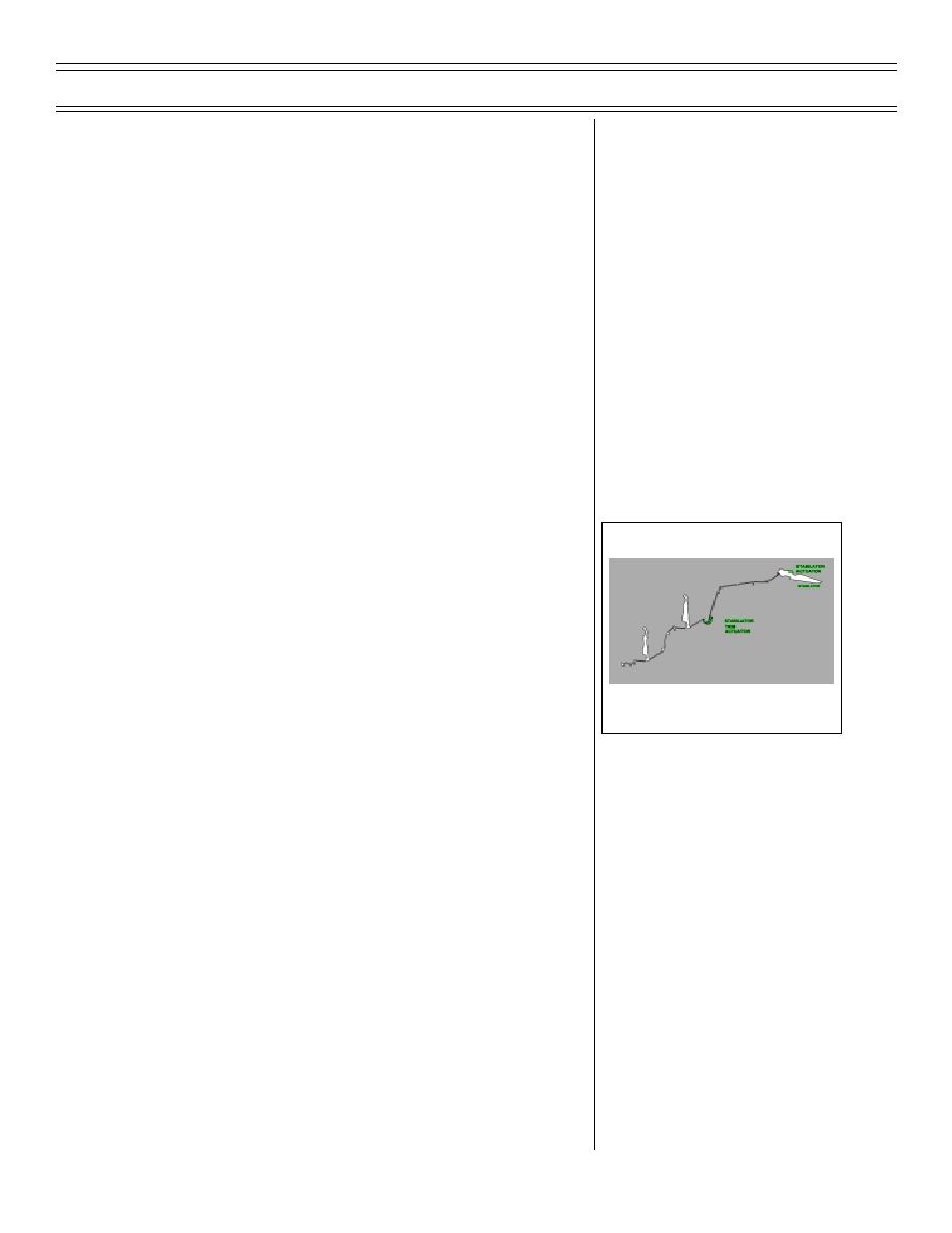
Stabilator system
Sg 5, fr 6
a.
Control surface components
(1) Stabilator: provides primary pitch
control
(2) Stabilator actuator provides me-
FLIGHT CONTROLS-
chanical power to move stabilator
STABILATOR SYSTEM COMPONENTS
via stabilator trim input
(3) Stabilator maximum trim is
8 degrees nose up and 3 degrees
nose down
(a) Main stabilator trim motor
powered by 28 VDC essential
services bus
(b) Standby trim motor powered
by 28 VDC generator bus
(4) Stabilator spring feel unit simu-
lates aerodynamic loading
b.
Cockpit controls/switches/indicators
(1) Aileron/stabilator trim switch
Page 26-49
(8-03) Original


 Previous Page
