T-45A UJPT, E2-C2, ADV, & IUT Eng-26
Engineering Review
(2) Standby stabilator trim switch
(guarded): located on each left
console
(3) STABILATOR position indicator:
located on left console, left of
aileron trim indicator
NOTE: Simultaneous operation of
trim switches in opposite directions
inhibits operation of the stabilator
trim main and standby motors.
3.
Rudder system
Sg 5, fr 7
a.
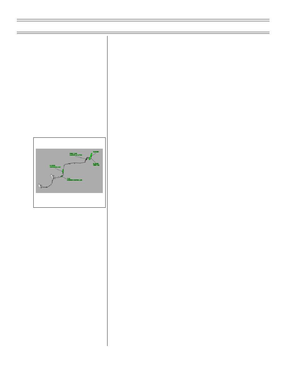
Control surface components
(1) Rudder
(2) Rudder trim tab
(3) Trim/Yaw damper actuator
FLIGHT CONTROLS-
RUDDER SYSTEM COMPONENTS
(4) Rudder centering unit
(5) Yaw damper controller
(6) Rudder pedal shaker and audio
tone activated when AOA exceeds
21.5 units
b.
Cockpit controls/switches/indicators
(1) Rudder pedals
(2) Rudder trim indicator
(3) RUDDER TRIM knob
(4) CONTR AUG switch
(5) CONTR AUG caution light
Page 26-50
(8-03) Original


 Previous Page
