T-45A UJPT, E2-C2, ADV, & IUT Eng-26
Engineering Review
f.
TONE button: left of LDG GEAR UP/
DN handle, both cockpits; silences
landing gear warning tone
3.
Operation: both NLG and MLG are
electrically controlled and hydraulically
operated
4.
Limitation: maximum airspeed for lowering
gear and flying with gear extended is
200 KIAS
K.
Landing gear-related hydraulic components
Sg 4, fr 6
1.
Brakes/anti-skid
a.
Major components
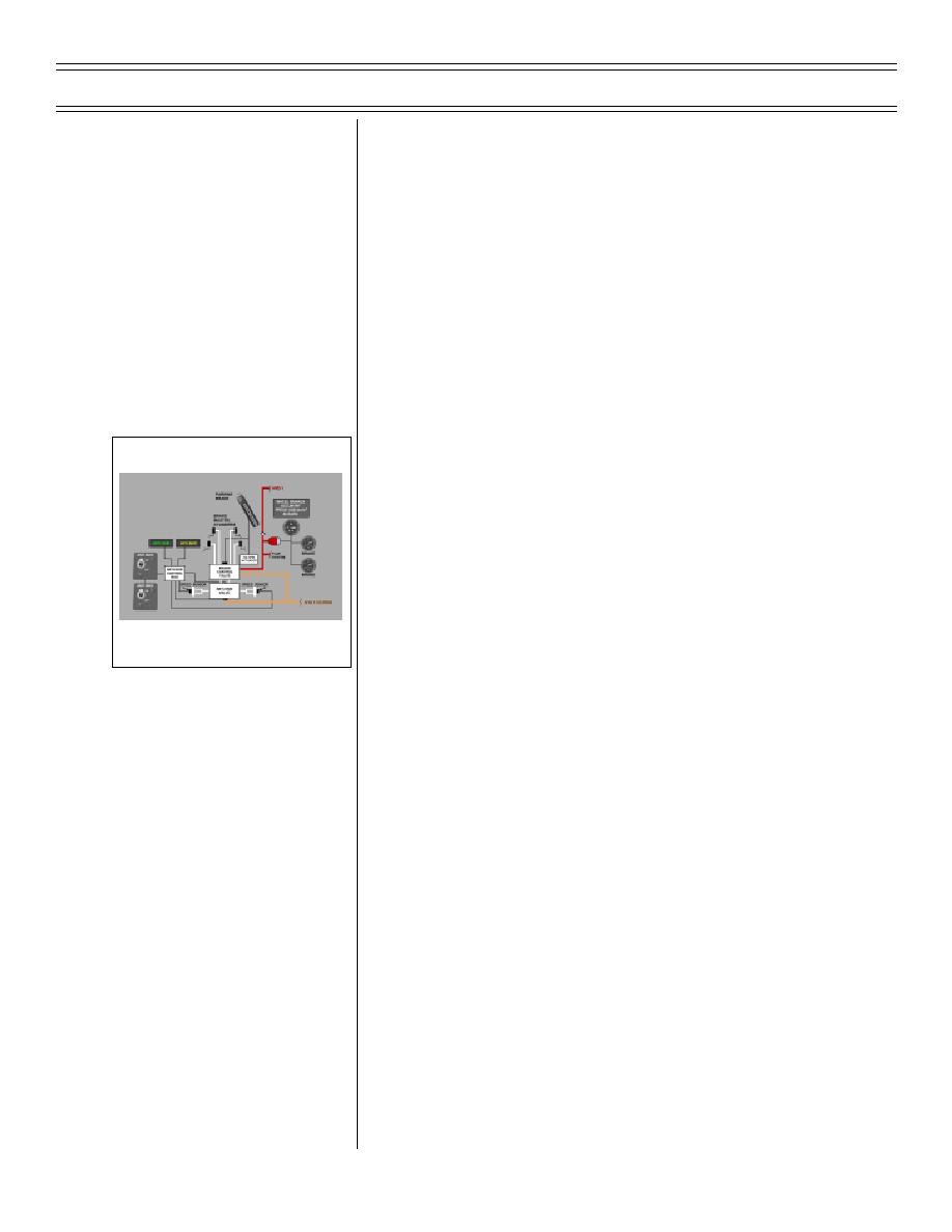
(1) Master cylinder: converts foot
pressure into hydraulic pressure
that controls brake control valve
WHEEL BRAKE/ANTI-SKID SYSTEM
BLOCK DIAGRAM
(2) Brake control valve: supplies
HYD 1 hydraulic pressure to oper-
ate wheel brakes whenever the
brake pedals are depressed, the
parking brake is engaged, or upon
command from the de-spin actua-
tor
(3) Anti-skid control valve: redirects
HYD 1 hydraulic pressure to the
return lines in response to inputs
from the anti-skid control unit
(4) Brake unit: transmits HYD 1
hydraulic pressure into mechanical
energy required to stop rotation of
main gear wheels
(5) De-spin actuator: signals brake
control valve to apply hydraulic
power to brake units to stop wheel
rotation when gear handle is raised
Page 26-36
(8-03) Original


 Previous Page
