T-45A UJPT, E2-C2, ADV, & IUT Eng-26
Engineering Review
IV. Hydraulic system and subsystems
Sg 4, fr 1
Lesson Organization
A.
Hydraulic system No. 1 (HYD 1) description:
The HYD 1 reservoir supplies fluid to the HYD 1
EDP which produces hydraulic pressure to
power the flight controls (ailerons and stabilator)
and aircraft general services (speed brakes,
flaps/slats, landing gear/gear doors, wheel/
parking brakes, nose wheel steering, launch
bar, and the arresting hook). Control of the
rudder is mechanical.
B.
HYD 1 components
1.
Engine-driven pump (EDP)
a.
Location: aft right side of engine
accessory gearbox
b.
Description
Sg 4, fr 2
(1) Functional
(a) Produces hydraulic pressure
for HYD 1
(b) Output volume varies in
response to demand
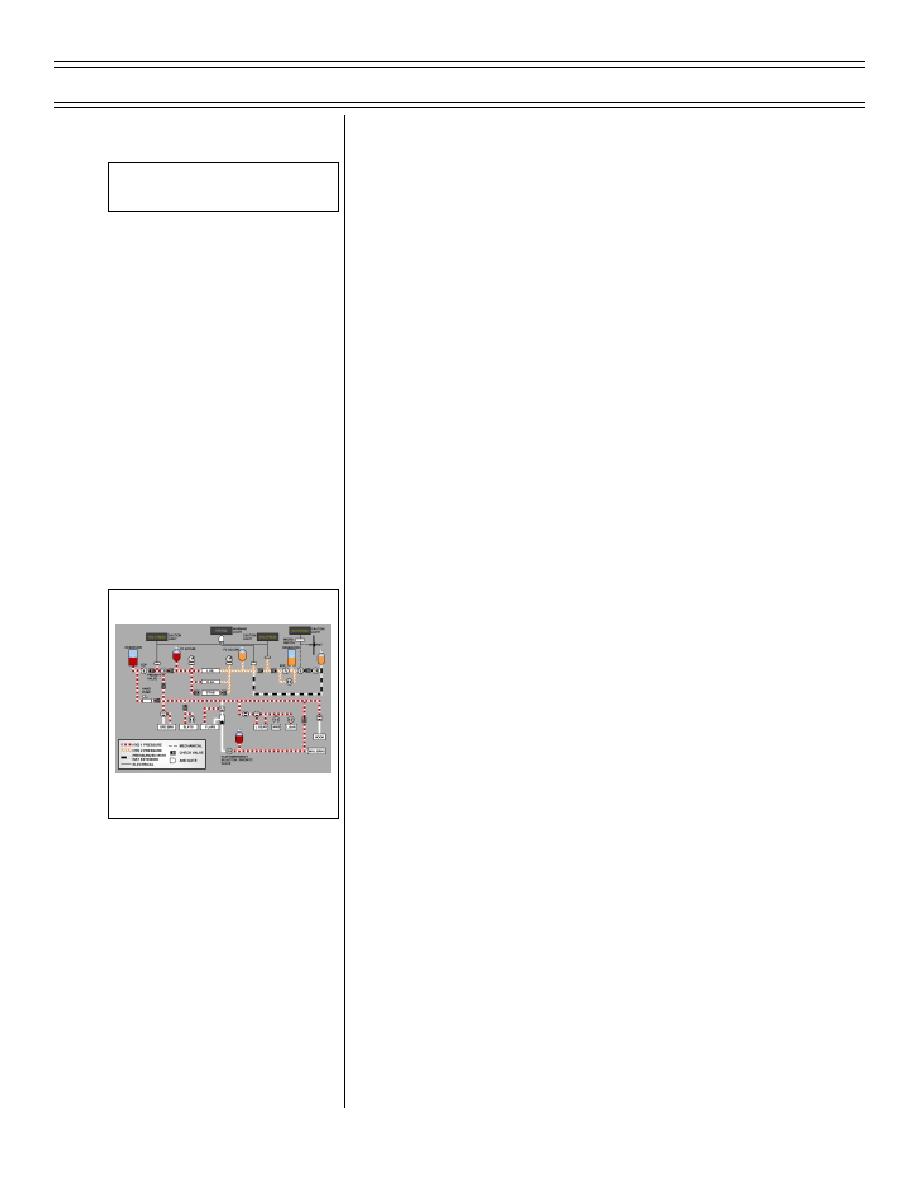
HYDRAULIC SYSTEM
BLOCK DIAGRAM
(2) Physical
(a) Variable displacement pump
(b) Constant (normal) output
pressure: 3,000 psi at
9.6 gallons per minute
NOTE: If normal 3,000 psi
exceeded due to system
failure, at 3,600 +/- 50 psi, a
hydraulic system pressure
Page 26-20
(8-03) Original


 Previous Page
