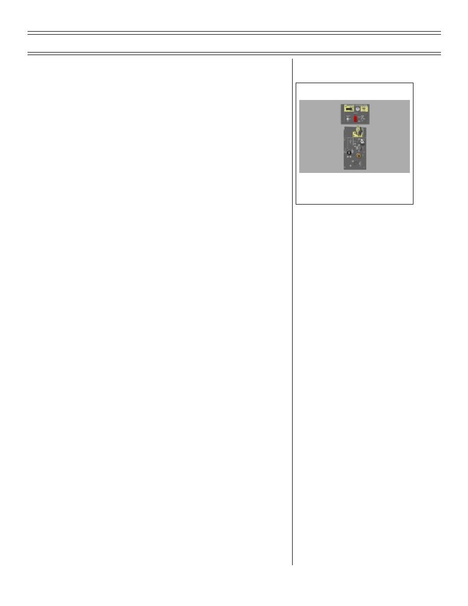
T-45A UJPT, E2-C2, ADV, & IUT Eng-26
Engineering Review
(1) NORMAL: enables engine ignition
Sg 11, fr 3
by closing electrical gate, allowing
28 VDC essential services bus
GTS START switches
(2) ISOLATE: disables engine ignition
by opening electrical gate, remov-
ing 28 VDC essential services bus
IGNITION AND ENGINE SWITCHES
AND PILOT SERVICES PANEL
and GTS START switches
(FWD COCKPIT VIEW)
NOTE: Battery switches must be
on for power to be present on the
28 VDC essential services bus.
2.
ENGINE switch
a.
Location: left console, aft of throttle,
both cockpits
b.
Description: three-position switch
marked ENGINE - OFF/ON/START
(spring-loaded from START to ON)
(1) ON: applies 28 VDC essential
services bus power to start control
unit (ENGINE switches in both
cockpits must be set to ON for
engine start)
(2) START: applies 28 VDC essential
services bus power to start control
unit, which provides start-engine
signal and
(a) Accelerates GTS to full power
(b) Opens start valve to admit air
to air turbine starter (ATS)
(c) Closes GTS air dump valve
Page 26-85
(8-03) Original


 Previous Page
