Aero Chapter 02, High-Speed Flight
T-45 Aerodynamics Student Workbook
VORTEX GENERATORS
Regarding efficient high-speed flight, it is undesirable to place vortex generators on any aircraft surface:
wing, tail, or fuselage. The obvious reason is that all add-on protuberances increase aircraft parasite
drag. Additionally, the need for vortex generators increases aircraft design time and overall cost.
Notwithstanding, at times wind tunnel and/or flight tests identify aircraft performance shortcomings in
critical flight regimes that must be corrected with vortex generators.
The primary purpose of vortex generators is to improve aerodynamic stability, performance, and/or flight
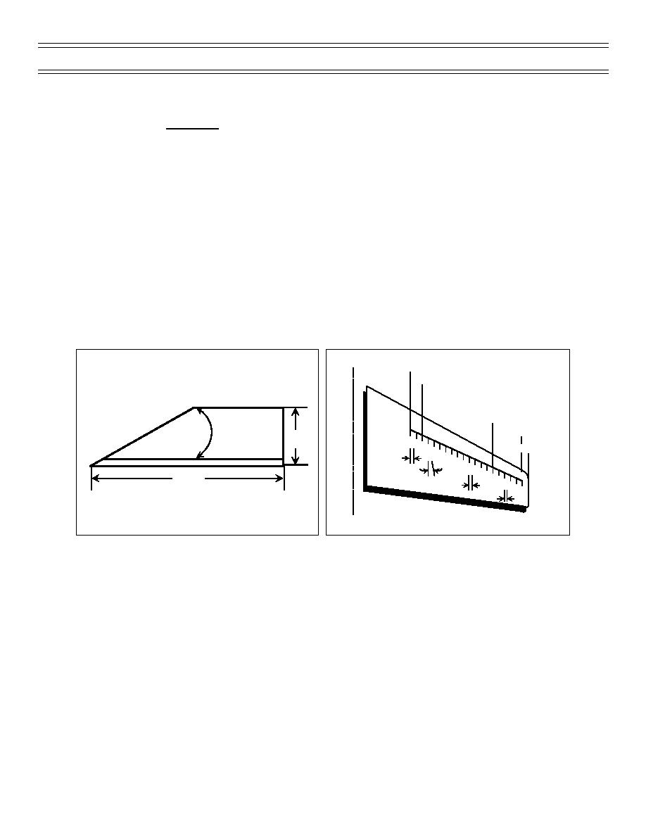
control effectiveness. They come in various sizes and shapes (Figure 39). On some aircraft, they are
utilized to improve stall performance. On others, they are used to improve flight performance in subsonic
and/or transonic flight realms.
During development of the T-45, it became necessary to add vortex generators to prevent wing downwash
from adversely affecting stabilator performance in the transonic flight regime. They were placed along the
25% chord line on the topside of the wing (Figure 40) to force wing downwash further below the stabilator,
thus eliminating some undesirable pitchup tendencies. Vortex generators also improve the aircraft’s slow-
speed flight performance by redirecting wing airflow and reenergizing the boundary layer.
CL
BL 2120.
VORTEX GENERATOR
PLANFORM VIEW
BL 2408.
Not To Scale
SIDE VIEW
25%
BL 4052.
CH
OR
D
BL 4589.5
30
17.
12
34
BL 4698.
10
56
144.
12
78
14
9
11
16
18
13
51.
10
20
15
137.
17
19
NOTE: All Dimensions in mm
107.5
Figure 39: VORTEX GENERATORS
Figure 40: VORTEX GENERATORS
RUDDER SHOCK STABILIZATION STRIPS
The T-45 rudder system is of conventional design. As flight velocity advances into the transonic range,
supersonic compression shock waves form on various parts of the aircraft. Some of those shock waves
were determined to cause a unique problem with the rudder that was not anticipated during original
aircraft design. Transonic regime shock waves were forming on and near the rudder assembly. The main
problem was that they were not maintaining a stable position. Consequently, the tail assembly
experienced “rudder buzz” problems. To eliminate “rudder buzz,” a rudder shock stabilization strip was
added to each side of vertical stabilizer, plus another to each side of the rudder. The specific effect of the
stabilization strips is to cause the transonic shock waves that form in this area to stop moving back and
forth, and to instead stabilize atop these add-on metal strips.
(7-99) Original
Page 23


 Previous Page
