Aero Chapter 02, High-Speed Flight
T-45 Aerodynamics Student Workbook
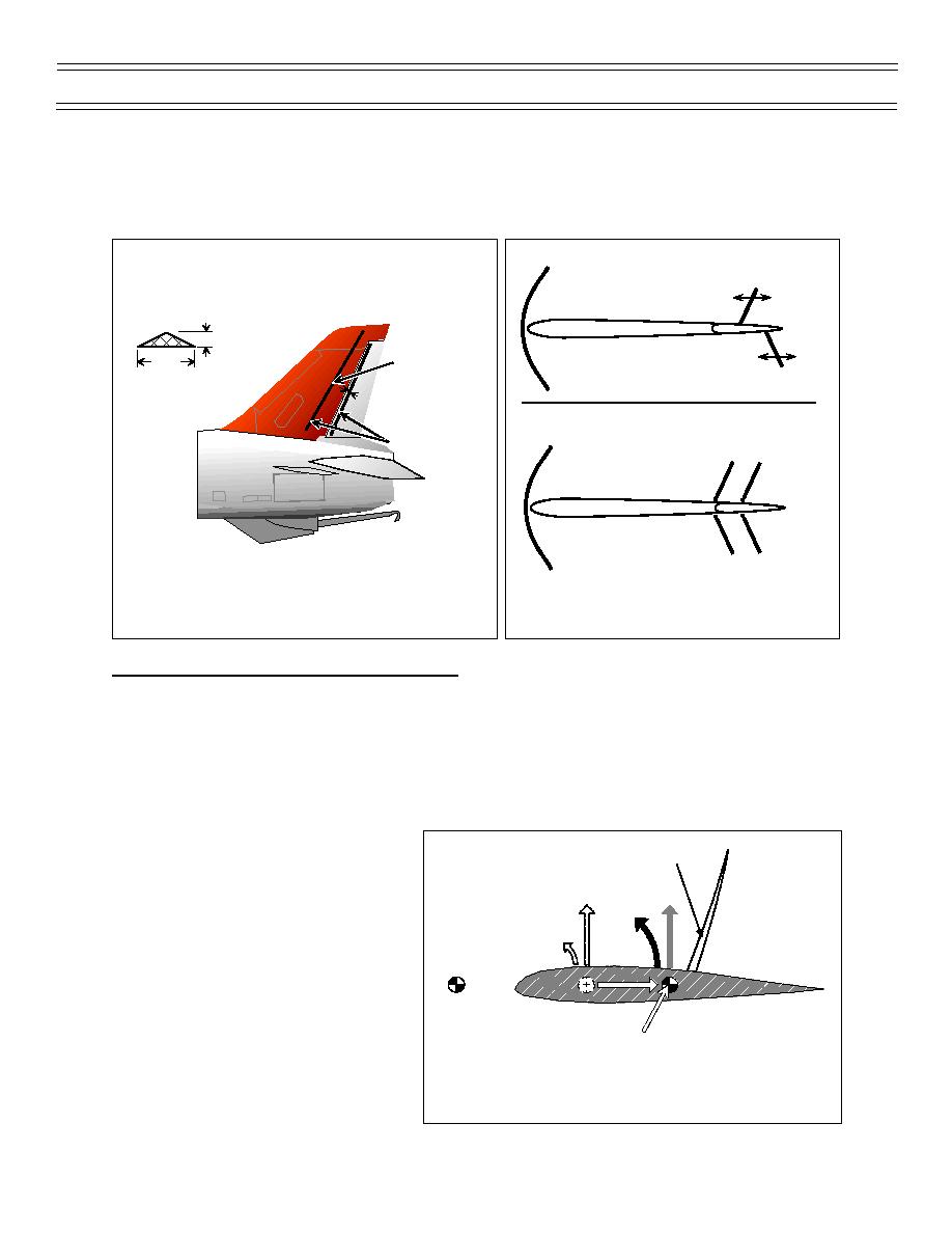
This “fix” has improved the situation, but has not eliminated “rudder buzz.” As shown in Figure 41, one
strip is located at the 50% tail chord position, and the other is on the rudder just aft of the rudder hinge
line. A cross-sectional depiction of the strips is also shown. Figure 42 is a top view of the fin and rudder.
Without Stabilization Strips
Moving
Shock Wave
Bow Wave
VERTICAL FIN
PLANFORM VIEW
Rudder
0.20"
50% Chord
0.70"
Moving
Cross Section of
Shock Wave
Rudder Shock
2.0"
Stabilization Strip
With Stabilization Strips
Added to Tail and Rudder
Rudder Shock
Stabilized
Stabilization Strips
Shock Wave
Bow Wave
Rudder
Stabilized
Shock Wave
Figure 42: RUDDER SHOCK
Figure 41: RUDDER SHOCK
STABILIZATION STRIPS (2 OF 2)
STABILIZATION STRIPS (1 OF 2)
T-45 HIGH-SPEED FLIGHT CHARACTERISTICS
SIGNIFICANT MACH NUMBERS
The T-45 is a transonic aircraft. The maximum level speed attained is 0.83 Mach with the maximum
speed achieved being 1.04 Mach. 1.04 Mach is attainable only in a dive in a clean configuration. The
critical Mach number of the T-45 is 0.8 Mach. The force divergent Mach number occurs at 0.85 Mach. As
airspeeds increase past 0.9 Mach, slight buffeting is felt that may increase as Mach number increases.
Between 0.92 and 0.95 Mach, some wing heaviness may be experienced.
LONGITUDINAL CONTROL
As the aircraft is accelerated above 0.8
Shock Wave
AS SHOCK WAVE APPEARS,
Mach, there is a slight nosedown pitch
AERODYNAMIC CENTER MOVES AFT
change as the aerodynamic center moves
aft. Longitudinal control is predictable to
about 0.84 Mach. At a Mach number
greater than 0.84 Mach, stick forces
become noticeably more sensitive and a
band of reduced longitudinal stability exists
at approximately 0.87 Mach. Above 0.95
Center of
Gravity
Mach, slight pitch oscillations may be
present as the center of pressure moves aft.
Aerodynamic Center
As airspeed increases above Mach 1.0,
stability increases and greater stick forces
Figure 43: AFT MOVEMENT OF THE CENTER
are required to affect a pitch change
OF PRESSURE
because of the aft location of the center of
pressure (Figure 43).
(7-99) Original
Page 24


 Previous Page
