Aero Chapter 02, High-Speed Flight
T-45 Aerodynamics Student Workbook
In contrast, the T-45 rudder is a
Direct mechanical connection between
conventional control system having
rudder pedals and control surface.
no hydraulic boost or electronic
assist (Figure 37). Aerodynamic
forces may cause rudder vibrations
that are fed back to the rudder
pedals through the mechanical
linkage and are called “rudder buzz.”
If the rudder “blows out” due to side
loads during a post-stall gyration
(PSG) or spin, the rudder pedals will
NO HYDRAULIC ASSIST TO CONTROL INPUTS.
be displaced and in excess of 250
pounds of force may be required to
FEEDBACK PROVIDED BY DIRECT LINKAGE.
center the rudder.
Figure 37: CONVENTIONAL CONTROL SYSTEM
HIGH-SPEED ENGINE
OPERATION
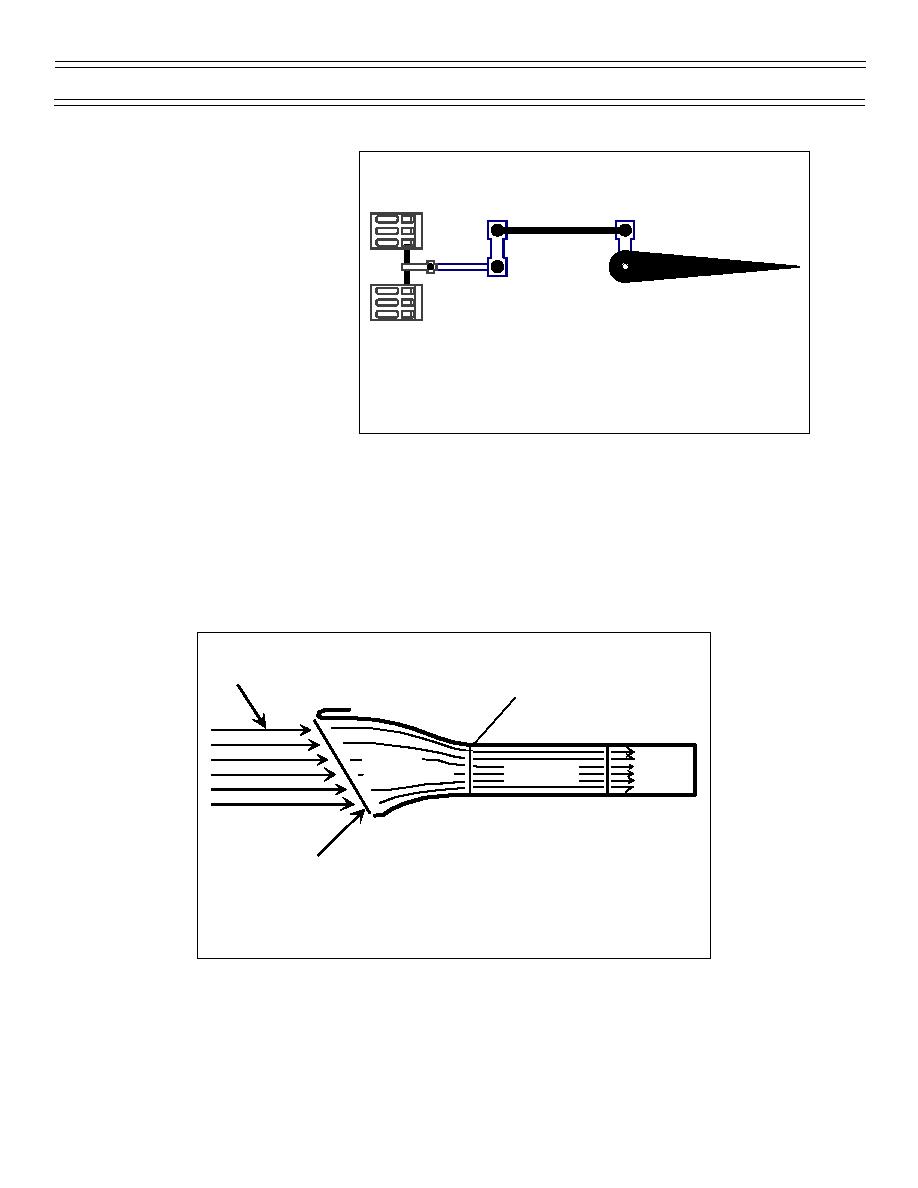
No operational turbojet or turbofan engine can ingest and operate with supersonic airflow. The shock
waves that would form on the fan or turbine blades would cause engine malfunction. Consequentially, in
transonic or supersonic flight, all intake airflow must be decelerated to subsonic velocity prior to reaching
the engine. Typically, deceleration takes place through a series of compression waves created by the
design of the aircraft’s intake (Figure 38). The airflow velocity will first be reduced to a slower supersonic
velocity by one or more oblique waves and then slowed to subsonic velocity through a normal wave. The
F-14 uses an adjustable inlet ramp system which reduces the inlet cross section in supersonic flight and
creates multiple oblique shock waves to slow the supersonic air.
Normal
Supersonic
Shock
Airflow
Wave
Slower
Subsonic
Engine
Supersonic
ENGINE INLET
Oblique
Shock
Wave
Figure 38: SUPERSONIC FLOW IN AN ENGINE INLET
Page 22
(7-99) Original


 Previous Page
