Aero Chapter 01, General Aerodynamics Review
T-45 Aerodynamics Student Workbook
The relative strength of static lateral stability to static directional stability may produce directional
divergence, spiral divergence or Dutch roll.
Directional divergence occurs as an aircraft yaws or rolls into a sideslip. Side forces cause increased yaw
indicating directional instability. Directional divergence is designed out of most aircraft.
Spiral divergence results from strong directional stability relative to weak lateral stability. Spiral
divergence will be discussed in a later lesson.
Dutch roll results from strong lateral stability relative to directional stability. Dutch roll will also be
discussed in a later lesson.
OPERATING ENVELOPE
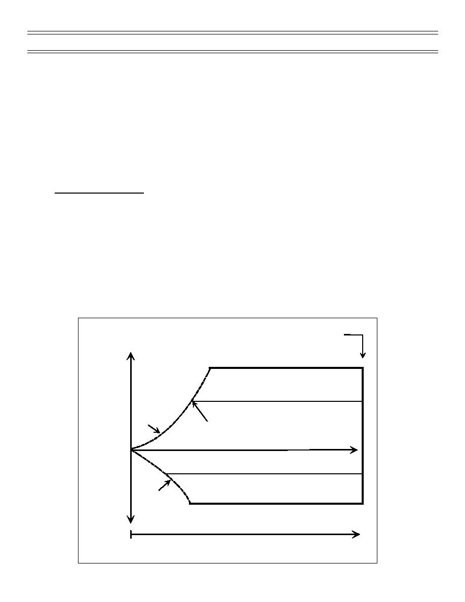
The NATOPS OPERATING ENVELOPE is often referred to as the Vg or Vn diagram. It is a graphic
representation of the operating envelope of the aircraft. Velocity is plotted on the horizontal in either
indicated airspeed (KIAS) or indicated Mach number (IMN). The vertical is plotted in either acceleration
(g) or wing load (n), thus the names Vg or Vn diagram. The plot will then depict the operational envelope
of the aircraft based on weight, configuration, altitude, and loading (symmetrical or unsymmetrical). The
structural limitations will be depicted vertically in either g or maximum wing load. The maximum velocity is
depicted on the horizontal in either KIAS or IMN. That plot, combined with the thrust curves, enables the
pilot to determine the maximum capability and restrictions of the aircraft.
Construction of the flight envelope graph is depicted in Figure 12. Aerodynamic limits define the
maximum positive and negative lift an aircraft can develop before stall occurs. The aerodynamic limits are
the accelerated stall curve for that aircraft. The aerodynamic limits indicate the available g or maximum
acceleration that can be developed.
Aeroelastic
Limit
FAILURE
ULTIMATE STRUCTURAL LIMIT, POSITIVE
+
DAMAGE
Stall
STRUCTURAL LIMIT, POSITIVE
Aerodynamic
Limit
Positive
Cornering
Speed
LOAD
FACTOR
0
G FORCE
STRUCTURAL LIMIT, NEGATIVE
Stall
DAMAGE
_
Aerodynamic
ULTIMATE STRUCTURAL LIMIT, NEGATIVE
Limit
Negative
FAILURE
VELOCITY INCREASE
0
Figure 12: ENVELOPE DIAGRAM
Page 9
(7-99) Original


 Previous Page
