Weapons Delivery Principles and Procedures
Weapons
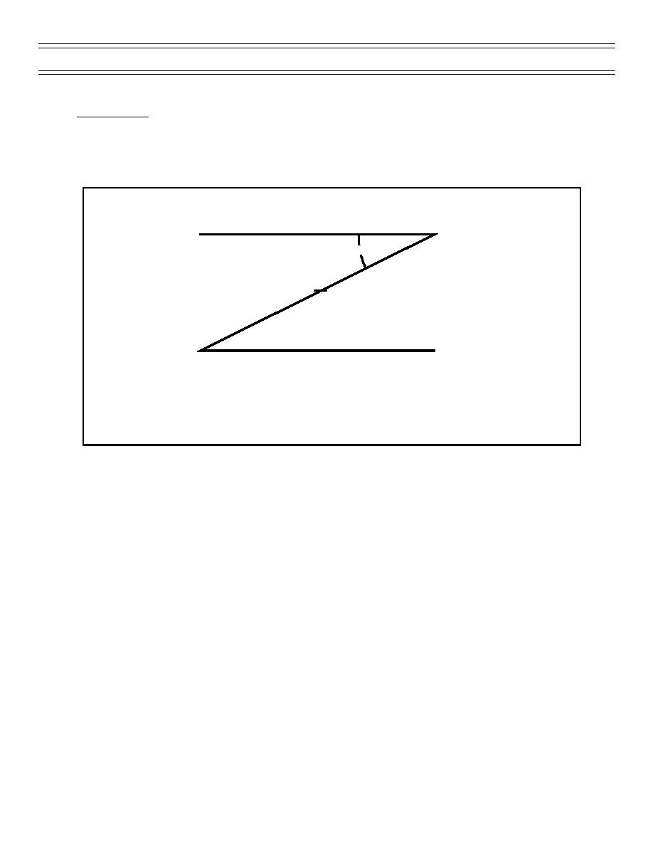
"Z" DIAGRAM
"Z" diagrams are useful presentations of pattern and weaponeering information included on briefing
boards and kneeboard cards (Figure 16).
Pattern Alt.
A/S
RPM
Dive Angle
Checkpoint Alt.
Initial Pipper Placement
Mil Setting
Release Alt.
Release TAS/IMN
Radalt Setting
Min. Release
Figure 16: THE "Z" DIAGRAM
THE BOMBING TRIANGLE
The geometry of an aircraft releasing a weapon in a dive is known as "the bombing triangle" (Figure
15). The base of the triangle is the horizontal distance downrange from the point of release to the
point of impact. The vertical component of the triangle is the release altitude, and the hypotenuse of
the triangle is the trajectory drop of the weapon. The angle between the flight path of the aircraft and
the ground is the dive angle.
The angular difference between the armament datum line (the "waterline") and the flight path of the
aircraft is the angle of attack. This angle is expressed in mils on the delivery data table (Figure 1). As
the aircraft accelerates in the dive, the angle of attack is reduced so that, at release, the ADL and the
flight path of the aircraft are nearly aligned.
When a bomb is released, gravity immediately starts pulling it down from the aircraft's flight path in an
arc towards the earth. From the point of release, the angular deflection from the flight path of the
aricraft to the point of impact is known as trajectory drop. The longer the time of flight, the longer
gravity has to act on the weapon and the greter the trajectory drop will be.
The sight angle is the angular difference (in mils) between the armament datum line and the impact of
the weapon. Therefore, the sight angle equals the angle of attack plus the trajectory drop of the weapon
(plus a couple of negligible mils of parallax.) In order to hit the target, the pilot must decide on a release
altitude and airspeed and consult the delivery data table to find the appropriate sight setting for that
attack.
Page 31
(4-03) Original


 Previous Page
