HUD
Weapons
display to the default mil setting for rockets or guns. Their mil settings can be changed with the SET
DEP key.
To set the continuously computed impact point (CCIP), press the MODE key after selecting one of the
air-to-ground modes on the weapons selector. Pressing the MODE key again will return the display to the
DSL submode. After entering air-to-ground data, set the weapons selector to OFF to return the HUD to
the navigation master mode.
The target data, submode (DSL
or CCIP), and the mil settings will
be retained in the HUD's memory
even if the HUD is switched to
another master mode or turned
5
5
off in flight. In the target area,
place the weapons selector to
BOMBS, ROCKETS, or GUN A/G
35
00
01
29.92
and press the station or gun
10
350
10
5,000
select switch as appropriate for
2,550 R
the weapon you are going to use.
1
T 375
5.0
Also set the VCR switch to ON or
120
M 0.42
AUTO as briefed. You can
G 1.0
BOMBS
15
update target data and change
2
15
mil settings in flight by following
the same procedures listed
3
above.
4
HUD AIR-TO-GROUND
SYMBOLOGY
In air-to-ground mode the aircraft
symbol is displayed on the
waterline, and bank angle indica-
tors are not displayed. Because
you are maneuvering in relation
to the target, your specific bank
angle is not important; the pitch
bars will still be displayed, and
you can use them as a wings
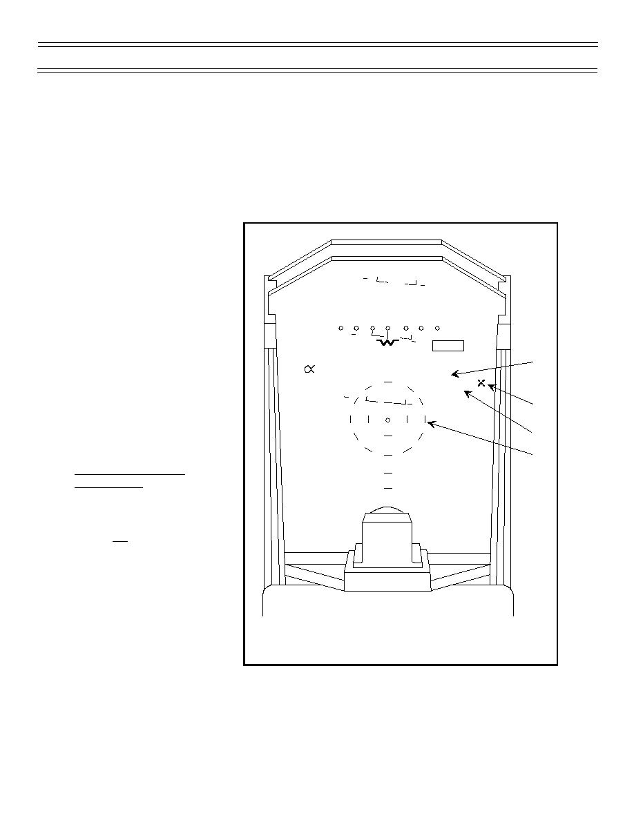
1. SUBMODE INDICATION (MILS DEPRESSION)
2. WEAPON RELEASE INDICATOR
level reference in the tracking
3. WEAPON TYPE/MASTER ARM INDICATOR
run.
4. DSL AIMING RETICLE
Figure 6: HUD A/G DSL DISPLAY (TYPICAL)
The "X" over BOMBS, indicating
that the master armament switch
on the weapons selector panel is set to SAFE, is removed when the master armament switch is set to
ARM. The DSL A/G aiming reticle consists of two concentric dashed rings around the pipper. The
inner ring has a radius of 25 mils and the outer ring has a radius of 50 mils. Below the outer ring are
two reference marks at 75 and 100 mils (Figure 8).
Page 10
(4-03) Original


 Previous Page
