Operational Navigation
Systems Navigation
waypoint string, and deselect (unbox) the SEQ DEP option. When a waypoint string of two or more
is entered in the waypoint string, the SEQ and AUTO option on the HSI display are enabled. When
SEQ is selected, the sequence steering string is displayed on the HSI as dashed lines (Figure 9).
Steering to any waypoint, not just those in the sequence string, is selected with the waypoint
increment/decrement arrows.
WAYPOINT AUTO SEQUENCE NAVIGATION
When the AUTO option is selected on the HSI display, any previously selected steering mode (TCN,
VOR/ILS, or WO/S) is deselected. WYPT is boxed, steering to the first waypoint in the stored
sequence is provided, and the course setting is set to the waypoint bearing. With AUTO sequence
selected, the waypoint increment/decrement selection arrows allow manual selection of the
waypoints contained in the sequence string in the order of the sequence string that was entered.
Selection of the last waypoint wraps to the first, and vice versa. As the aircraft proceeds along the
route entered in the string, the steering automatically increments to the next waypoint in the string
and the course setting is updated to the new leg bearing. This automatic waypoint change occurs
when the range to the selected steer-to waypoint is less than five nautical miles and the difference
between the waypoint bearing and aircraft ground track transitions from less than to greater than
ninety degrees. Upon reaching the last waypoint in the sequence string, AUTO is unboxed and
steering to the last waypoint in the string is
retained.
NOTE: When a closed loop sequence is entered
[the first and last waypoint in the string are the
AUTO
SEQ
SCL
W
same and the pilot has sequenced through the
T
80
Y
C
161o / 60.7
P
waypoint string manually], the pilot must ensure
N
10:07
T
12
E
TOW E R
that the active waypoint displayed is the first one
15
in the string, not the last one.
6
6
S
WAYPOINT NAVIGATION HSI DISPLAYS
6
3
P
L
CDI MODE
A
N
21
360 GS
N
The CDI mode (Figure 9) for waypoint or
W318o / 12
C
waypoint offset steering is similar to the TACAN
D
24
I
C
33
mode, except that the CDI deviation reference
R
S
W
30
scale dots represent deviation in nautical miles,
A
D
and the scaling varies based on landing gear
I
161
089
CRS
AFT
DATA
MENU
position. With the landing gear UP, full scale
HDG
deflection ( two dots) of the inner CDI bar
represents 4.0 nautical miles of cross track
deviation. With the landing gear down, full scale
Figure 11: WAYPOINT AUTO-SEQUENCE
deflection represents 0.3 nautical miles of
NAVIGATION PLAN
cross track deviation.
PLAN MODE
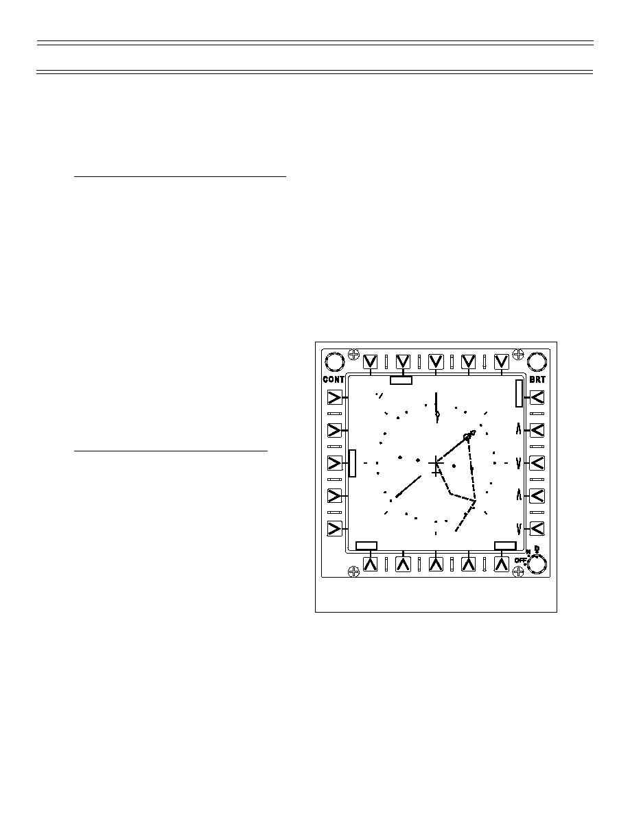
The PLAN mode (Figure 11) for waypoint or waypoint offset steering is identical to TACAN. The
course line is drawn through the waypoint or waypoint offset symbol that is displayed inside the
compass rose parallel to the selected course. If the waypoint or waypoint offset is not displayed,
distance greater than the compass rose scale, the course line is drawn on the edge of the compass
rose parallel to the selected course. The course deviation and intercept angle are shown by the
relationship of the aircraft symbol to the planimetric course line.
In Figure 11 the aircraft just overflew the previous waypoint in the string and is turning to waypoint
number 6. Waypoint steering and course were automatically changed to waypoint number 6 when
the previous waypoint was overflown.
(4-03) Original
Page 24


 Previous Page
