 |
|||
|
|
|||
|
Page Title:
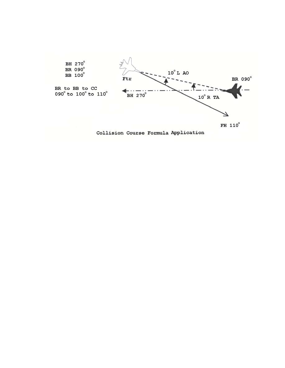
Figure 7 Collision Course Formula Application |
|
||
| ||||||||||
|
|  INTERCEPT PROCEDURES TEXTBOOK
The first collision course correction method goes one step further. Since it is known that AO
must equal TA in a co-speed environment:
Example:
Figure 7
The intercept triangle can be visualized on the face of a BDHI with the center representing
the intersection of the two flight paths. Note that the dashed bogey bearing line can be
transposed to the center of the BDHI. Since the two dashed lines are parallel, they form equal
angles when cut by a transversal line represented by the bogey or the fighter flight path. Note
that the TA and AO within the intercept triangle can be depicted within the cut, where they are
shown to be equal to each other but opposite in direction.
The previous example (Figure 7) illustrated right TA, where we added the degrees from BR
to BB and then added that same number of degrees (continuing in the same direction) to find the
collision course.
Collision Course Correction Formula 2
Further CCCs with a contact on the scope will be done according to the second formula.
This method is important since the GCI controller's bogey bearing calls are less accurate than the
radar scope information. After the bogey is on the scope, aircrew can read AO directly off the
scope and compare it with the cut. The purpose is still to make AO equal in quantity but
opposite in direction to TA.
48
|
|
Privacy Statement - Press Release - Copyright Information. - Contact Us |
