 |
|||
|
|
|||
|
|
|||
| ||||||||||
|
|  CHAPTER SEVEN
T-34C CONTACT
Continue to fly the aircraft from the 90 position and anticipate a rate of turn which
will enable you to intercept the extended centerline with 85 KIAS FF/95 KIAS NF,
1200-1500 feet of straightaway, 100-150 feet AGL, and wings level. Check and
report on the ICS, "Gear down, paddles checked." (If no paddles are available, report
"negative paddles.")
The need for corrections in the approach must be recognized as soon as possible and
the actual corrections must be small to avoid over correction. Although power
controls the rate of descent and the nose attitude controls the airspeed, it must be
remembered that the combination of attitude (nose and wing) and power work
together to produce aircraft performance. Any change in attitude (nose or wing) to
maintain the proper glidepath will require a corresponding change in power. No
written outline can effectively state all possible errors in a landing approach. The
correctional techniques that are utilized to correct for deviations from the desired
altitude/airspeed are those learned on your first flight. Remember, the combination of
attitude and power work together to produce aircraft performance.
e.
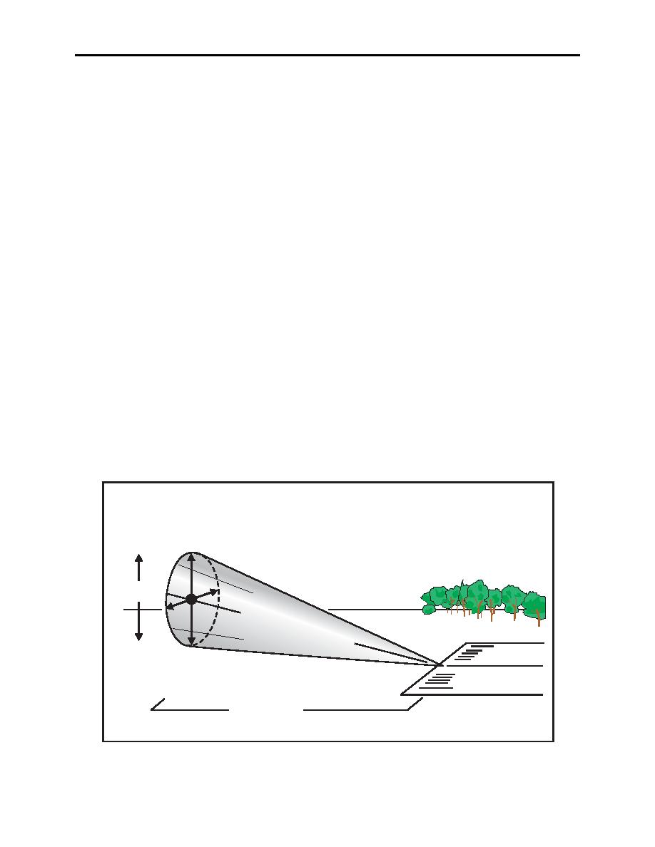
The "final" (straightaway or groove) is that final portion of the landing approach,
beginning at a point 1200-1500 feet from the intended point of landing at an altitude
of 100-150 feet AGL where the aircraft is first aligned, wings-level and ends with the
landing transition. The length of the straightaway should provide 10-12 seconds prior
to landing. (Figure 7-5).
The entire pattern to this point is designed to position the aircraft to intercept the cone
that is the glideslope groove. The rate of descent must be adjusted and readjusted in
order to achieve and maintain a constant rate of descent, but also to stabilize the
glideslope "picture." Power required will vary with wind conditions.
150' AGL
50'
"G r o
ove
"
100' AGL
1200' - 1500'
Figure 7-5 The "Groove"
7-10 LANDING PROCEDURES
|
|
Privacy Statement - Press Release - Copyright Information. - Contact Us |
