 |
|||
|
|
|||
|
|
|||
| ||||||||||
|
|  CHAPTER ELEVEN
T-34C AIRCRAFT SYSTEMS FAMILIARIZATION
WORKBOOK
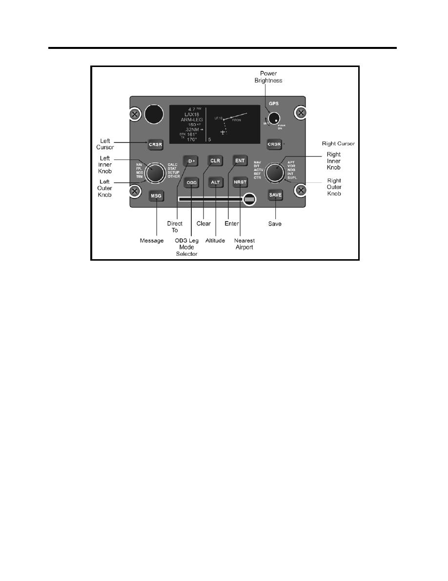
Figure 11-6 KLN900 GPS
NOTE
The front unit must be on and functioning properly for either unit to
be used for navigation. The last input from either cockpit has
priority for system control.
The KLN900 system includes two KLN900 display /control panels, two KA41
Annunciator/Control Panels (Figure 11-7), one KA90 slaving accessory, one blind cockpit
encoding altimeter, and one GPS antenna. The slaving accessory is located on the top shelf in the
avionics compartment. The GPS antenna is mounted adjacent to the NACWS GPS antenna on
top of the fuselage behind the rear cockpit. The blind encoding altimeter is located in the front
cockpit, mounted aft of the inverters on the left kick panel.
The NAV and GPS annunciators of the KA41 annunciator/control panel indicate the slaving
source for the double needle on the RMI and CDI. The white NAV light indicates the double
needle on the RMI is slaved to the TACAN and the CDI is slaved according to the position of the
VOR/TACAN toggle switch. The green GPS light indicates the double needle and CDI are
slaved to the KLN900. The GPS/NAV button, below the lights, is used to select either navigation
source.
The KLN900 allows you to control and view your flight plan data. The power/brightness control
is located in the upper right corner of the unit. It is a pull-off/push-on control for power and
rotate for brightness type control.
11-10 AVIONICS
|
|
Privacy Statement - Press Release - Copyright Information. - Contact Us |
