T-45C TS, ADV, & IUT RIFP-01
Introduction to Radio Instruments
B.
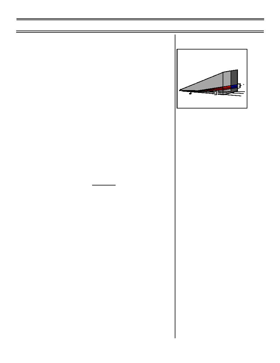
Glideslope transmitter
Sg 11, fr 5, p2
1.
Produces a navigational signal which
ILS LOCALIZER COMPONENTS
provides vertical guidance for the pilot
(glidepath) along the localizer approach
course
1.4
.7
.7
2.5
NOTE: The ILS beam gradient (glideslope)
2.5
3
is normally set for a 3-degree glidepath.
GLIDESLOPE SIGNAL
However, the angle may be set to other
gradients due to terrain or obstacle
clearance and/or reception requirements.
NOTE: "Glideslope" is defined as the
descent angle assigned to an approach for
a given runway for the reasons stated
above. Normally the term is associated with
the final descent angle of an ILS or PAR
approach. "Glidepath" is defined as that
portion of a precision approach where the
glideslope intersects the localizer beacon of
an ILS or FAC of a PAR.
2.
Located 750 ft - 1,250 ft down the
designated ILS runway offset 250 ft - 600 ft
from centerline
NOTE: Glideslope frequencies are paired
to localizer frequencies and are
automatically tuned upon selection of
localizer frequency.
3.
The beam usable range: 10 nm, provided
aircraft is on localizer course (may be
certified for extended service volume which
exceeds 10 nm)
a.
Intersects inner marker beacon
approximately 100 ft above runway
elevation
b.
Intersects middle marker beacon
approximately 200 ft above runway
elevation
(5-99) Original
Page 1-35


 Previous Page
