T-45A UJPT, E2-C2, ADV & IUT Eng-13
Hydraulic Subsystems
b.
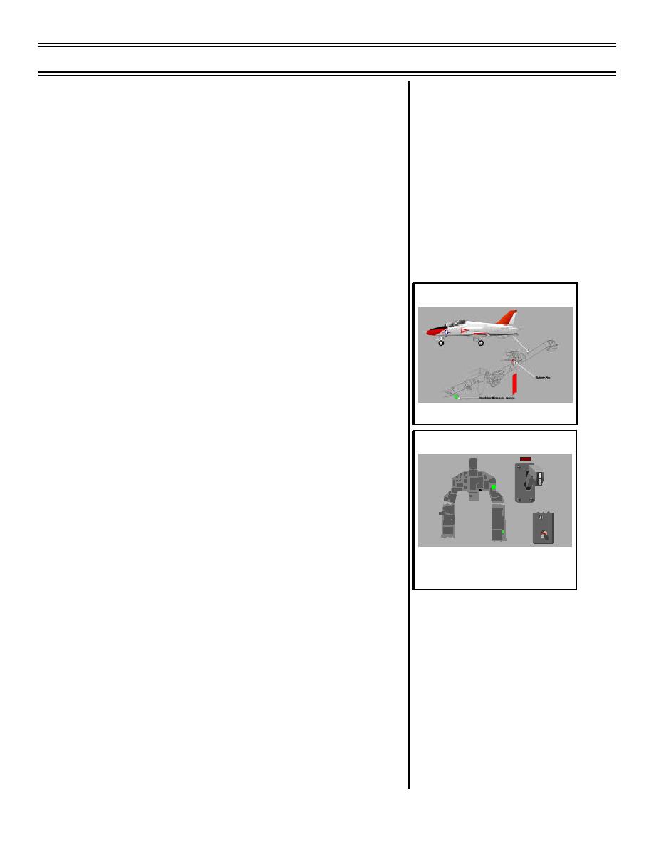
Oleo-pneumatic centering unit
(1) Buffers against lateral shock loads
(2) Spring unit keeps tail hook
centered
c.
Arresting hook assembly: engages
deck arresting cable or field arresting
gear to stop aircraft
d.
Uplatch mechanism: mechanically
Sg 2, fr 16
retains arresting hook in up position
e.
Arresting hook safety pin
2.
Controls and indicators 1.4.13.3
a.
Arresting HOOK handle
Arresting Hook Inspection
(1) Location: right side of instrument
panel, both cockpits
Sg 2, fr 17
HOOK
(2) Purpose
(a) Extends hook when pushed
down
HOOK BYPASS
CARRIER
FIELD
(b) Retracts arresting hook when
ARRESTING HOOK SYSTEM
pulled up (handle is normally
CONTROLS AND INDICATORS
(FWD COCKPIT)
in up position)
(c) Fore and aft cockpit handles
are interconnected and move
together
b.
Arresting HOOK warning light
(1) Location: above HOOK handle,
right instrument panel, both
cockpits
(8-03) Original
Page 13-43


 Previous Page
