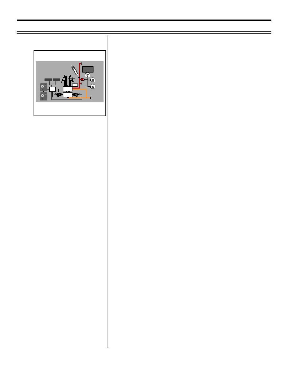
Hydraulic Subsystems
T-45A UJPT, E2-C2, ADV, & IUT Eng-13
b.
Brake control valve: supplies HYD 1
Sg 2, fr 3
hydraulic pressure to operate wheel
HYD 1
HYD
brakes whenever the brake pedals are
PARKING
BRAKE
WHEELBRAKES
ACCUM INF
P
2
A
PRESS 1300 lbs/in
R
depressed, the parking brake is
K
86BARS
I
N
BRAKE
G
MASTER
B
R
2
0
A
CYLINDERS
K
10
E
30
0
40
engaged, or upon command from the
2
1
3
ANTI-SKID
ANTI-SKID
0
4
PSI
X
1000
BRAKE
FLAP
ANTI-SKID
de-spin actuator
SYSTEM
DE-SPIN
ACTUATOR
O
N
2
1
3
0
4
BRAKE
PSI
OFF
ANTI-SKID
X
1000
CONTROL
CONTROL
BRAKE
VALVE
BOX
SPEED SENSOR
SPEED SENSOR
ANTI-SKID
ANTI-SKID
O
N
VALVE
c.
Anti-skid control valve: redirects HYD 1
OFF
HYD1RETURN
hydraulic pressure to the return lines in
WHEEL BRAKE/ANTI-SKID SYSTEM
BLOCK DIAGRAM
response to inputs from the anti-skid
control unit
d.
Brake unit: transmits HYD 1 hydraulic
pressure into mechanical energy
required to stop/slow rotation of main
gear wheels
e.
De-spin actuator: signals brake control
valve to apply hydraulic power
(pressure) to brake units to stop wheel
rotation when main gear is raised
NOTE: When gear handle in cockpit is
moved to UP position, HYD 1 pressure
from left main gear inner door open line
is routed to brake control valve to apply
brake pressure.
f.
Parking brake: mechanically operates
brake control valve to apply hydraulic
pressure simultaneously to both wheel
brake units to park aircraft
g.
Anti-skid control unit: "brains" of anti-
skid system; controls operation of anti-
skid valve
h.
Speed sensors: measure rotation
speed of each wheel; resulting signal
sent to anti-skid control box and used
to predict when a wheel is about to skid
Page 13-18
(8-03) Original


 Previous Page
