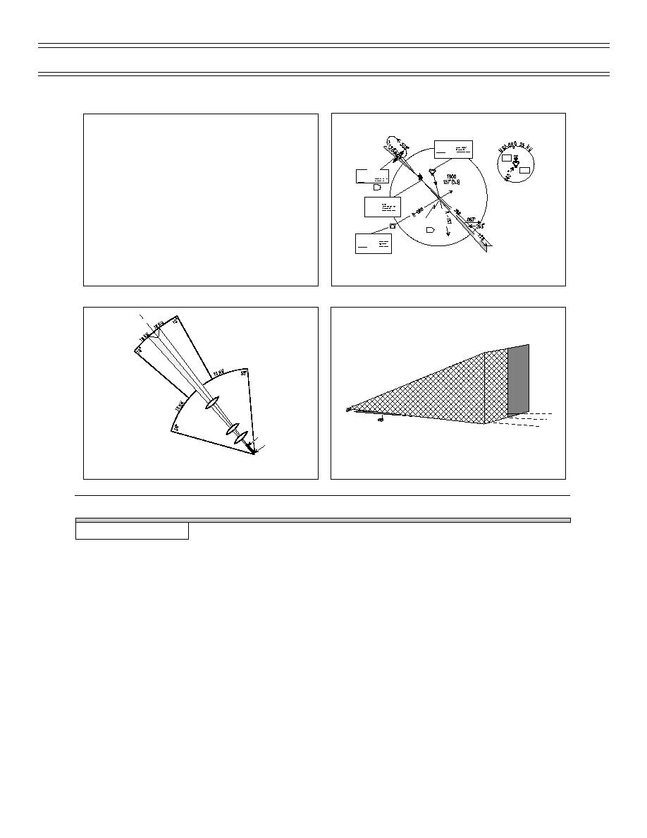
ILS Procedures
E2-C2 BIFP-06 & IUT BIFP-05
Sg 1, fr 3
Sg 1, fr 2
INTRODUCTION TO RADIO INSTRUMENTS
BROWNSVILLE
116.3 BRO
Chan 110
*
Elements of an ILS approach
2600
*
ILS approach procedures
LOM
1600
DEPOO
393 BR
I-BRO 7.4
LOCALIZER 110.3
I-CRP
Chan 40
(IAF)
CALIA INT
I-BRO 4.9
MATAMOROS
114.3 MAM
Chan 90
BACK COURSE LOC APPROACH
Sg 1, fr 5, pg 1
Sg 1, fr 4
ILS LOCALIZER COMPONENTS
OM
2.5
MM
2.5
IM
Runway
Localizer Antenna
LOCALIZER BEAM
LOCALIZER SIGNAL USABLE RANGE
PRESENTATION
I.
Elements of an ILS approach 22.9.4.6.5, 22.9.4.6.1.1.1
A.
Localizer
1.
Provides azimuth for front and back course
approach (unless antenna shielded from back
course)
2.
Usable range: 35 degrees within 10 nm and 10
degrees within 18 nm of course centerline unless
published approach depicts a transition beyond this
range
3.
Beam width is 5 degrees wide, 2 1/2 degrees either
side of centerline
(03-97) Original
Page 5-3


 Previous Page
