T-45A UJPT, ADV, & IUT ACMFP-01
Introduction to ACM
Aeroelastic
Limit
(Redline)
ULTIMATE STRUCTURAL LIMIT POSITIVE
+
Cornering
STRUCTURAL LIMIT
POSITIVE
Speed
Aerodynamic
Limit
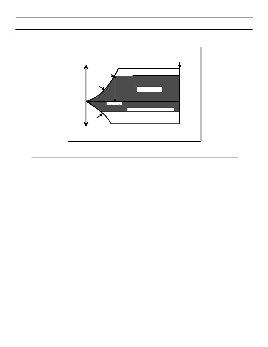
The Envelope
Positive
Sg 1, fr 6
LOAD
FACTOR
g FORCE
VELOCITY
STRUCTURAL LIMIT NEGATIVE
Aerodynamic
-
ULTIMATE STRUCTURAL LIMIT NEGATIVE
Limit
Negative
Vn DIAGRAM
C. Operational maneuverability--changes in altitude, airspeed and
direction limited by fixed and variable factors
1.
Fixed factors 6.7.2.3
a.
Structural limitations
(1) Maximum lift that can be supported by airframe
structure without yielding
(2) Maximum g capability--lift/gross weight (limitations
vary with fuel/ordnance loads)
(3) Operating envelope (Vn diagram) displays load factor g
limitations
b.
Thrust-to-weight
(1) Thrust varies with altitude and temperature
(2) Independent of airspeed (jet aircraft)
(3) Ratio equals aircraft thrust divided by combat weight
(4) Used to compare performance of aircraft
(10-98) Original
Page 1-11


 Previous Page
