T-45C TS, ADV & IUT ENG-13
Flight Control System
3.
Operating characteristics/limitations
Fwd/Aft Aileron/
Fwd/Aft
Stabilator Trim Switches
Control Sticks
Stabilator Spring
Stabilator
Feel Unit
Trim Actuator
Stabilator
PCU/Actuator
Stabilator
LEGEND
HYD 1
HYD 2
MECHANICAL LINKS
ELECTRICAL
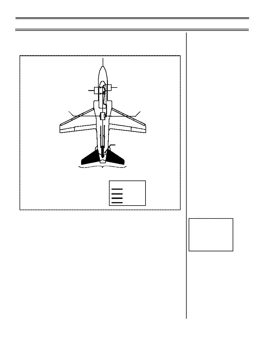
Figure 7: STABILATOR SYSTEM COMPONENTS -- SIMPLIFIED
Sg 2, fr 19
a.
Stabilator powered by tandem hydraulic
Fig 7: Stabilator
actuator: failure of either hydraulic system will
System Components--
not affect operation
Simplified
b.
Stabilator trim actuator consists of main and
standby motor
(1) Main motor powered by 28 VDC essential
bus. Operated by trim switch on control
stick
(2) Standby motor powered by 28 VDC gen-
erator bus. Used in case of main motor
failure. Controlled by STBY STAB TRIM
switch
(9-98) Original
Page 13-15


 Previous Page
