T-45C TS, ADV & IUT ENG-11
Hydraulic Subsystems
c.
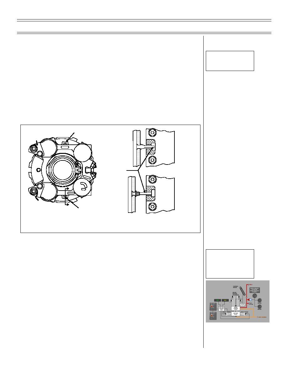
Wheel brake wear indicators
Sg 2, fr 9
Fig 14: Brake Unit
(1) Parking brake must be set
Inspection
(2) Brake wear indicators (two per wheel) must
protrude beyond bottom of recess in brake
housing
(3) Unacceptable condition is indicated by flush
or recessed indicators
Wear Pin
Service
Not
Required
Wear Pin
Service
A
Is
Required
A
Wear Pin
A-A
Figure 14: BRAKE UNIT INSPECTION
Sg 2, fr 10
d.
With both ANTI-SKID switches ON, hydraulic
Wheel Brake/Anti-
pressure from brake control valve is regulated
Skid System Block
by anti-skid valve which is controlled by anti-
Diagram
skid control box
(1) Speed sensors on both wheels send
relative rotation speed to anti-skid control
box
(2) When speed sensor senses an impending
skid, the anti-skid control box signals anti-
skid valve to reduce brake pressure on both
wheels. As wheel rotational speed
recovers, brake pressure is reapplied to a
level just below that which caused the skid.
(9-98) Original
Page 11-27


 Previous Page
