Hydraulic Subsystems
T-45C TS, ADV & IUT ENG-11
(2) Purpose: connected to master cylinder,
used to operate brake control valve which
in turn routes braking pressure to each
wheel
2
1
3
0
4
p.s.i.
X 1000
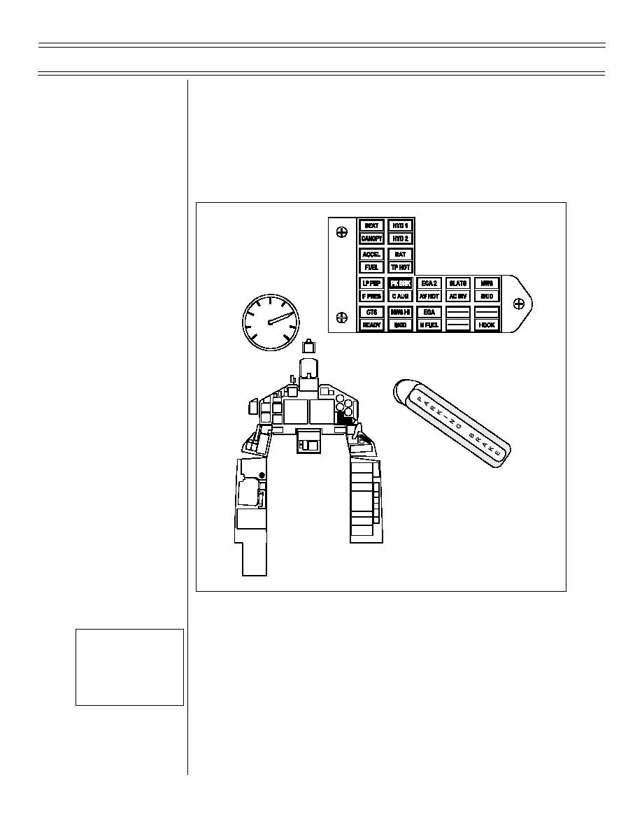
Figure 11: BRAKE SYSTEM CONTROLS AND INDICATORS
b.
BRAKE pressure gauge
Sg 2, fr 5
Fig 11: Brake
System Controls
(1) Location: left console, both cockpits
and Indicators
(2) Purpose: displays nitrogen pressure in
wheel brake/emergency flap accumulator
(same as wheel brake/emergency flap
accumulator pressure gauge in right main
wheelwell)
(9-98) Original
Page 11-22


 Previous Page
