 |
|||
|
|
|||
|
|
|||
| ||||||||||
|
|  CHAPTER THREE
INSTRUMENT FLIGHT RULES WORKBOOK
318. NOTES SECTION
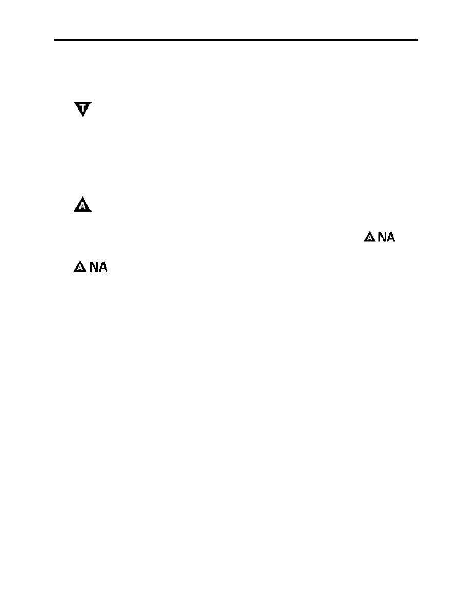
Viewing the same Kissimmee Municipal approach, notice the remarks and symbols located at the
bottom of the approach plate.
The
symbol indicates that takeoff minimums are nonstandard and/or special IFR departure
procedures are published. IFR departure procedures not published as graphic Departure
Procedures and take-off minima are included below and are established to assist pilots in
obstacle avoidance. Refer to appropriate service directives for take-off minimums. The take-off
minimums do not apply to military pilots. Our take-off minimums are determined by
OPNAV 3710.7 or appropriate service branch regulations. Airports with departure
procedures and/or takeoff minimums are listed alphabetically by airport name in the front of the
approach plates booklet.
The
symbol indicates civilian nonstandard IFR alternate minimums apply to this field.
Again, this does not apply to military pilots because our alternate minimums are determined by
OPNAV 3710.7 or appropriate regulations, but they must be checked to see if an
condition applies to all.
Symbol indicates that the approach minimums are not authorized for alternate
The
selection due to unmonitored facility or the absence of a weather reporting service. This symbol
DOES apply to Navy/Marine Corps pilots.
319. AIRPORT DIAGRAM/SKETCH
The airport diagram/sketch contains a plan view of the runways, location of obstructions at the
airport and other information essential to safe flight. Below the diagram box, the timing from the
FAF to the Missed Approach Point is listed for different ground speeds if timing is used for that
approach. Ground speeds must be estimated by the pilot based upon the most current wind
information. Take the time to familiarize yourself with the various symbols located around the
airport sketch.
320. APPROACH IDENTIFICATION
You have already learned that the information on the top left and lower left-hand corners identify
the approach that is portrayed in the plan view.
The first element of approach identification is derived from the type of facility providing final
approach course guidance. The second level of identification based upon the (a) runway number
when the approach course is within 30 of the runway centerline or (b) sequential lettering for the
airport when the approach course is more than 30 from runway centerline (e.g., VOR A, VOR
B, etc.).
3-18 INSTRUMENT APPROACH PROCEDURES
|
|
Privacy Statement - Press Release - Copyright Information. - Contact Us |
