 |
|||
|
|
|||
|
Page Title:
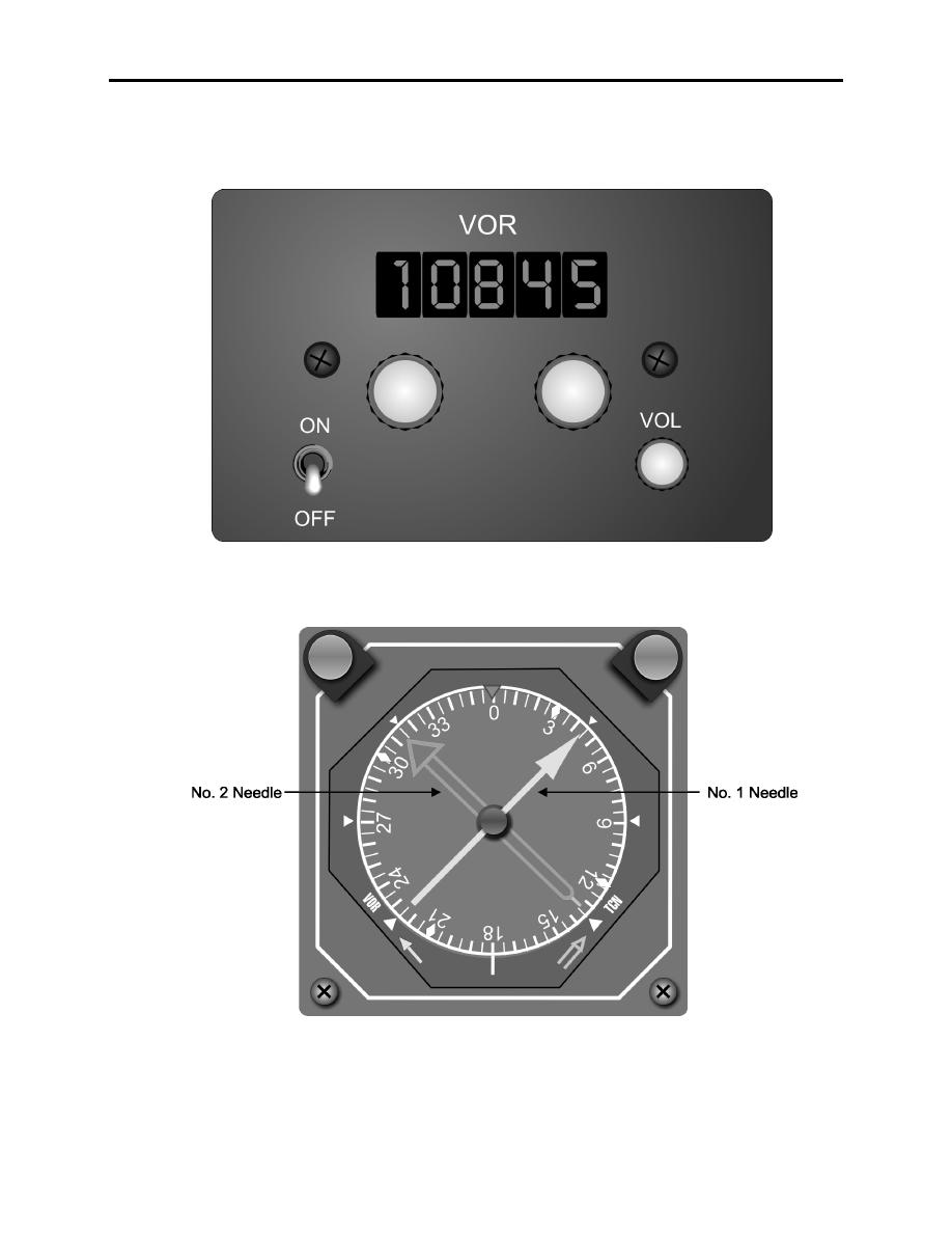
Figure 1-3. Radio Magnetic Indicator |
|
||
| ||||||||||
|
|  INSTRUMENT FLIGHT RULES WORKBOOK
CHAPTER ONE
VOR receivers provide the pilot magnetic bearing information and are capable of receiving voice
transmissions. The bearing information is displayed on the No.1 needle of the radio magnetic
indicator (RMI) (Figures 1-2 and 1-3).
Figure 1-2 VOR/VIR-30A Control Panel
Figure 1-3 Radio Magnetic Indicator
INTRODUCTION TO AIRBORNE NAVIGATION AND COMMUNICATIONS
EQUIPMENT AND PRINCIPLES OF OPERATION 1-5
|
|
Privacy Statement - Press Release - Copyright Information. - Contact Us |
