 |
|||
|
|
|||
|
Page Title:
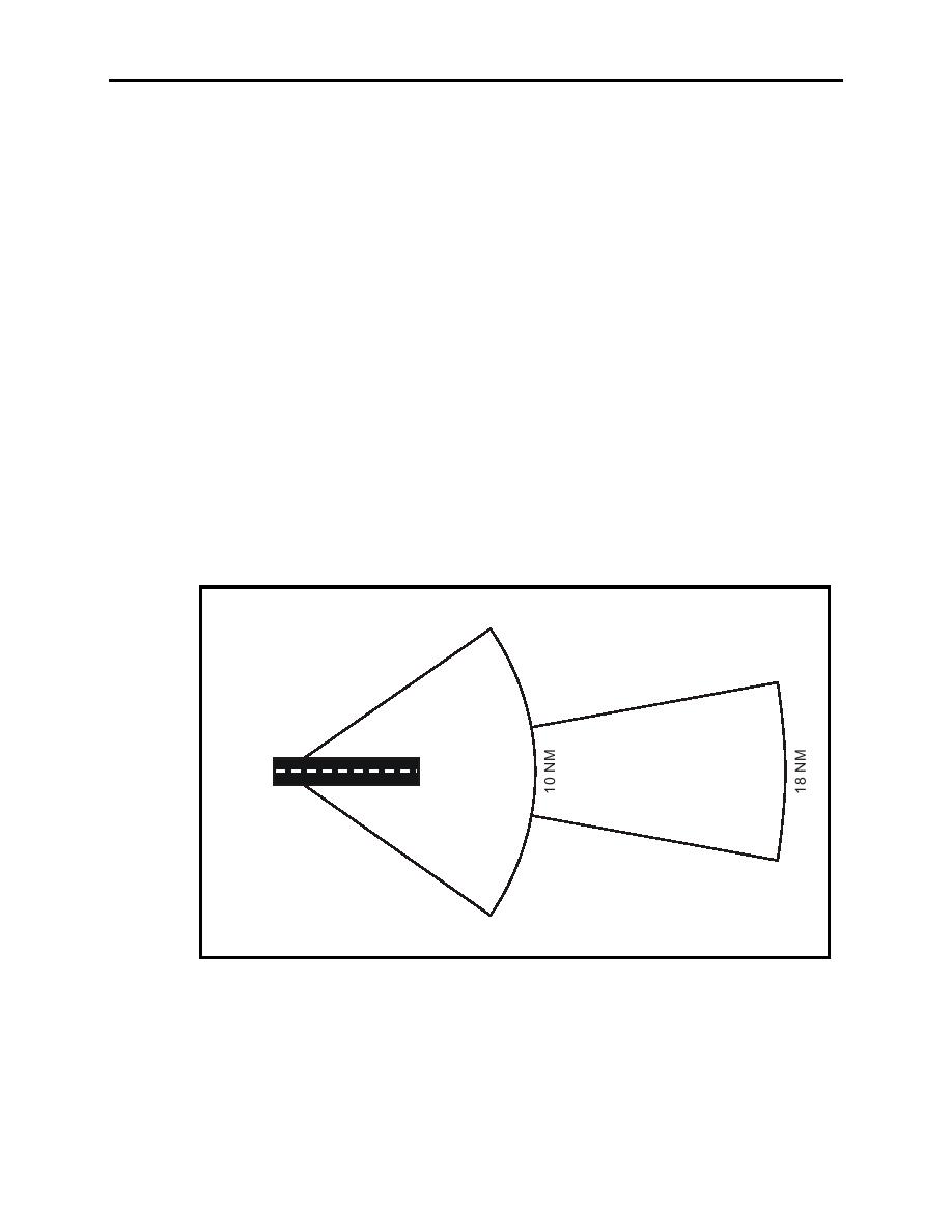
Figure 1-1 Limits of LOC Coverage |
|
||
| ||||||||||
|
|  T-6A INSTRUMENT NAVIGATION
CHAPTER ONE
unless a BC approach procedure is published for that particular
runway and the approach is authorized by ATC.
Identification is in International Morse Code and consists of a three-letter identifier preceded by
the letter I (●●) transmitted on the LOC frequency.
EXAMPLE: I-DIA. The LOC provides course guidance throughout the descent path to the
runway threshold from a distance of 18 NM from the antenna between an altitude of 1000 feet
above the highest terrain along the course line and 4500 feet above the elevation of the antenna
site. Proper off-course indications are provided throughout the following angular areas of the
operational service volume (Figure 1-1):
1.
To 10 either side of the course along a radius of 18 NM from the antenna.
2.
From 10 to 35 degrees either side of the course along a radius of 10 NM.
3.
Unreliable signals may be received outside these areas.
The UHF glideslope transmitter, operating on one of the 40 ILS channels within the frequency
range of 329.15 MHz to 335.00 MHz, radiates its signals in the direction of the LOC front
course. The term glidepath means that portion of the glideslope intersecting the LOC.
35
10
LOCALIZER
ANTENNA
10
NORMAL LIMITS OF LOCALIZER
COVERAGE: THE SAME AREA
APPLIES TO A BACK COURSE
35
WHEN APPROVED.
Figure 1-1 Limits of LOC Coverage
INTRODUCTION TO NAVIGATION SYSTEMS 1-7
|
|
Privacy Statement - Press Release - Copyright Information. - Contact Us |
