 |
|||
|
|
|||
|
|
|||
| ||||||||||
|
|  CHAPTER FIVE
STUDENT GUIDE FOR T-1A AIRCRAFT SYSTEMS
10. State when the landing gear warning tone will sound.
11. Discuss the emergency brake system.
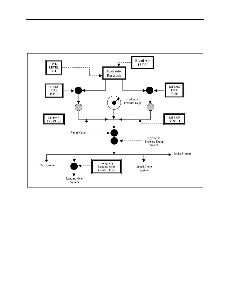
Figure 5-1 Hydraulic System
503. HYDRAULIC PUMPS
A variable displacement, rotary-plunger type pump is mounted on and driven by each engine
accessory gearbox. Each pump's delivery and pressure varies from 0 gpm at 1500 psi to 3.9 gpm
at 1400 psi. These pressure changes result from actuation of the hydraulic components.
5-2 HYDRAULIC POWER SUPPLY & SYSTEMS
|
|
Privacy Statement - Press Release - Copyright Information. - Contact Us |
