 |
|||
|
|
|||
|
Page Title:
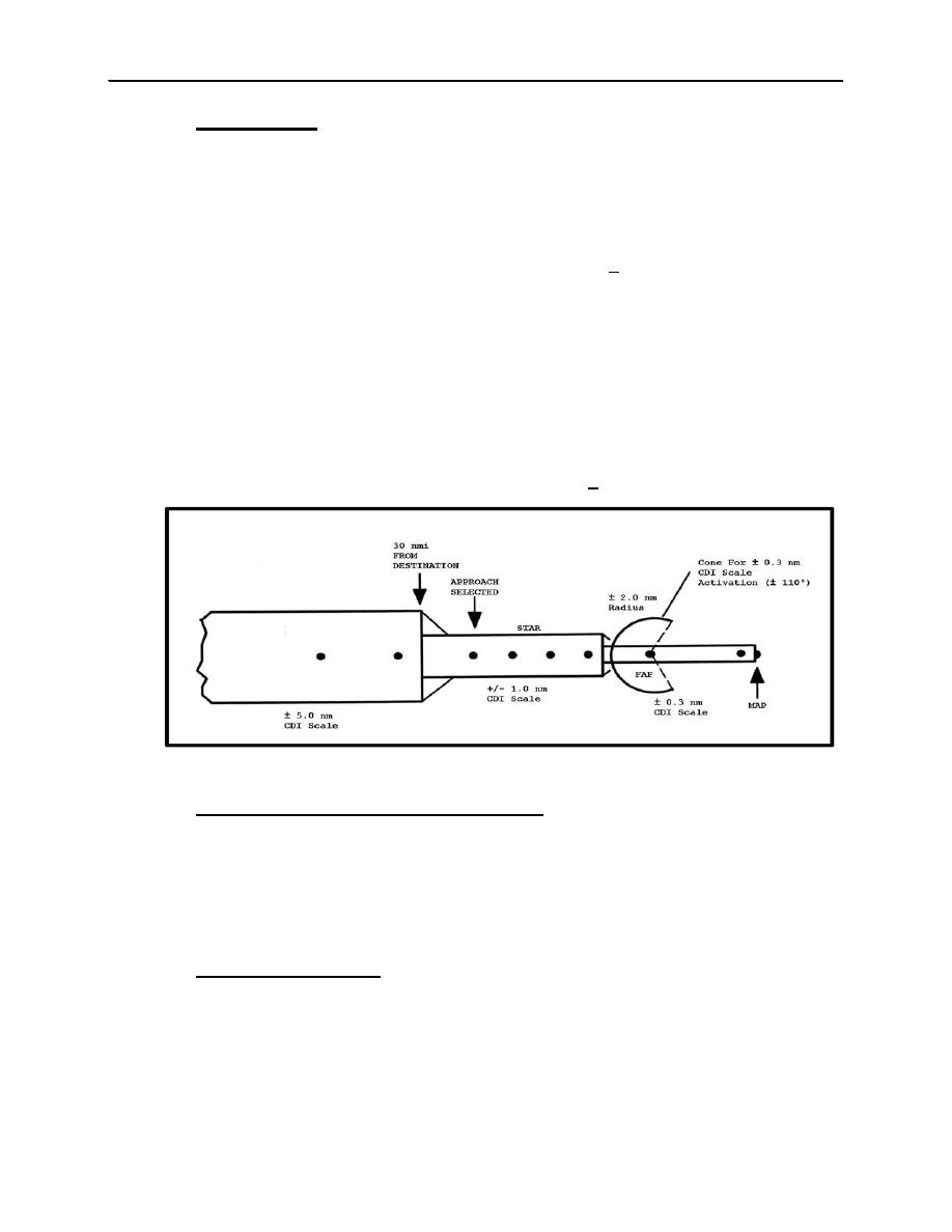
Figure 410-1. Course Sensitivity and CDI Scaling |
|
||
| ||||||||||
|
|  JOINT ADVANCED MULTI-ENGINE T-44A
E. Course Sensitivity.
The Course Deviation Indicator (CDI) sensitivity related to GPS equipment varies with the mode of
operation. Unlike traditional ground-based navaids, GPS course sensitivity is normally linear
regardless of the distance from the waypoint. The following modes provide the indicated CDI scaling
(see figure 411-1):
Terminal Mode. Terminal area operations are operations conducted within 30 nm of the destination
airport on charted SIDs/DPs/STARs or other flight operations between the last enroute waypoint and
an initial waypoint. CDI full deflection during these operations is + 1 nautical mile.
Enroute Mode. During the enroute phase, prior to the execution of the instrument approach, the
display sensitivity is a full-scale deflection of 5 nm either side of centerline.
Approach Mode. Upon activation of the approach mode, the display sensitivity should smoothly
transition from a full-scale deflection of 5 nm either side of centerline to 1 nm either side of centerline
within 30 nm of the destination airport. The approach mode must be active to proceed past the FAF on
a non-precision approach.
Final Approach Mode. At a distance of 2 nm inbound to the FAF waypoint, the display sensitivity
begins to transition to a full-scale deflection of 0.3 nm either side of centerline.
Missed Approach Mode. When navigation to the missed approach holding point is activated, the CDI
display sensitivity transitions back to terminal area sensitivity (+1 nm).
Figure 410-1. Course Sensitivity and CDI Scaling
F. Receiver Autonomous Integrity Monitoring (RAIM).
GPS equipment certified for IFR use must have the capability of verifying the integrity of the signals
received from the GPS constellation. The integrity of the GPS signal is verified by determining if the
integrity solution is out of limits for the particular phase of flight, if a satellite is providing corrupted
information, or if there is an insufficient number of satellites in view. When the integrity of the GPS
information does not meet the integrity requirements for the operation being performed, the aircraft's
GPS avionics will provide a warning in the cockpit. A GPS integrity warning in the cockpit is
equivalent to an "off flag" on your HSI; your GPS navigation information may no longer be reliable.
G. GPS Approach Restrictions.
There are several important operating restrictions when using GPS.
Instrument approaches must be accomplished in accordance with approved instrument approach
procedures retrieved from the FMS database using the current update cycle.
Instrument approaches must be conducted in the FMS Approach mode, and GPS integrity
monitoring (RAIM) must be available at the FAF, as indicated to the pilot by the INTG
annunciator being extinguished.
4-60
RADIO INSTRUMENTS STAGE
|
|
Privacy Statement - Press Release - Copyright Information. - Contact Us |
