 |
|||
|
|
|||
|
Page Title:
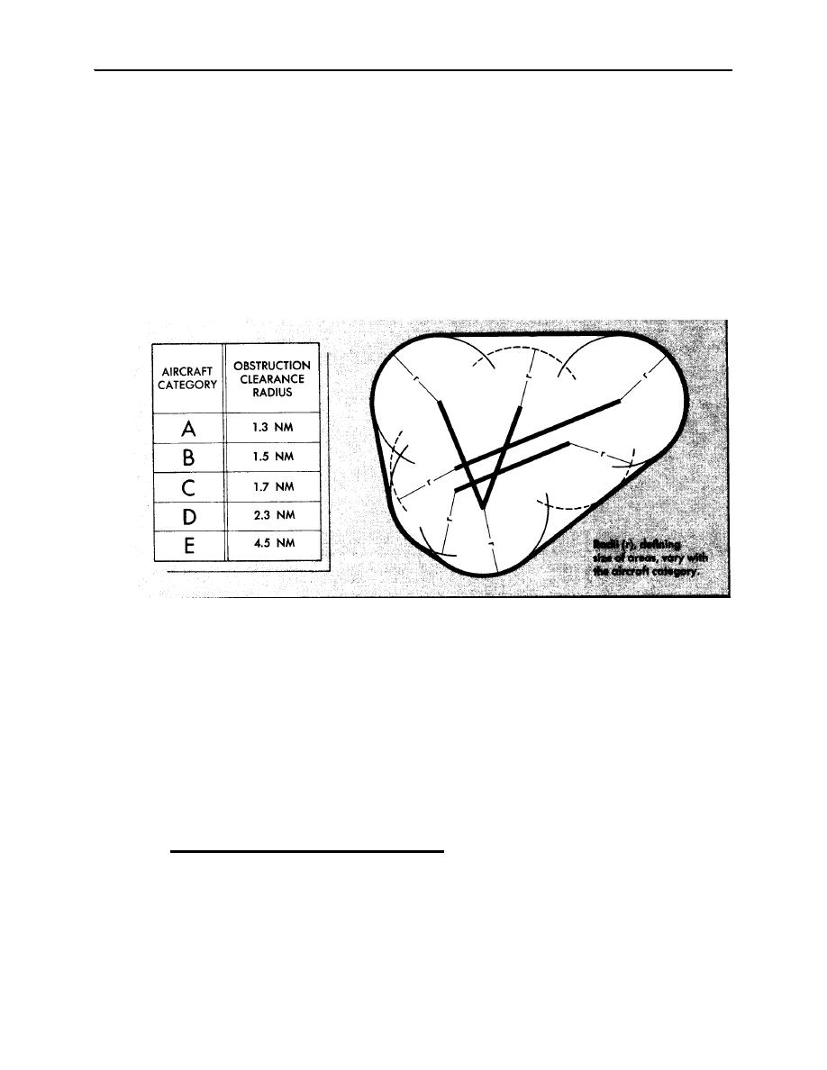
Figure 408-1. Circling Obstruction Clearance Area |
|
||
| ||||||||||
|
|  JOINT ADVANCED MULTI-ENGINE T-44A
or reduce airspeed below 120 KIAS until in a position to place the aircraft on a normal glidepath to the
landing runway. (In order to prepare students for the worst situation, fly practice circling approaches
at the circling MDA if feasible and conditions permit.)
Weather -- Low Ceiling/Restricted Visibility. If weather does not permit circling above the MDA, do
not descend below circling MDA or reduce airspeed below 120 KIAS until in a position to place the
aircraft on a normal glidepath to the landing runway (sometimes called the "VFR pattern checkpoint").
Missed Approach. If you lose visual reference while circling to land or there is any doubt whether the
aircraft can be safely maneuvered to touchdown, execute the missed approach (see section 409).
CAUTION: Be aware of the common tendency to maneuver too close to the runway at altitudes lower than your
normal VFR pattern altitude. This is caused by using the same visual cues you use from normal VFR pattern
altitudes. Select a pattern that displaces you far enough from the runway allowing you to turn to final without
overbanking or overshooting final.
Figure 408-1. Circling Obstruction Clearance Area
Single Engine Circle. The approach should be flown as described above in section 408 "Single Engine
Non-Precision Approach." The circling maneuver, especially single engine, can be one of the most
demanding requirements of a pilot (depending on daylight, weather conditions, etc.); it is critical to
maintain precise control of airspeed and altitude while visually aligning the aircraft to the landing
runway. When in a position to place the aircraft on a normal glidepath to the landing runway, extend
the gear and complete the Landing Checklist as you transition to land. However, during SSE training
ensure the gear is down no later than the 90 position.
NOTE: As during all non-precision approaches, if an engine fails or must be shutdown after the aircraft has
already been fully configured, it is normally necessary to raise the flaps and gear immediately and adjust power on
the available engine to maintain airspeed (unless the aircraft is approaching the 90 position and/or is in a safe
position to descend from the circling MDA for transition to land).
D. Fresnel Lens Optical Landing System (FLOLS).
Information on this particular lighting system is included since it is not described well in the FIH. This
system is an electro-optical pilot landing aid (see figure 409-2). It was designed primarily for use by
Navy aboard ship. However, most Naval Air Stations also have the FLOLS installed.
Purpose. The purpose of the system is to provide a visual indication of relative position with respect to
a prescribed glide slope. This glide slope is normally coincident with the precision approach glide
slope and designed to touch the aircraft down at a suitable distance prior to the arresting gear.
4-54
RADIO INSTRUMENTS STAGE
|
|
Privacy Statement - Press Release - Copyright Information. - Contact Us |