 |
|||
|
|
|||
|
|
|||
| ||||||||||
|
|  HELICOPTER AERODYNAMICS WORKBOOK
CHAPTER 5
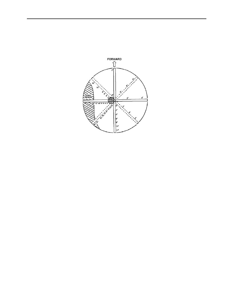
Figure 5-2 shows a rotor disk that reached a stall condition on the retreating side. It is
assumed the stall AOA for this rotor system is 14. Distribution of AOA along the blade is
shown at eight positions in the rotor disk. Although the blades are twisted and have less pitch at
the tip than at the root, AOA is higher at the tip because of less induced flow or flow coming
from below due to flapping.
Figure 5-2
Upon entry into blade stall, the first effect is generally a noticeable progressive vibration of
the helicopter. The vibration will be a two-to-one beat (2 vibrations per 1 revolution). This will
terminate in a loss of longitudinal control and severe feedback in the cyclic control. The nose of
the helicopter will oscillate up and down violently, independent of cyclic position. Corrective
action can be taken before stall becomes severe. Onset of blade stall varies with the following:
1. Airspeed
2. Gross weight
3. Density altitude
4. G loading (including high AOB turns and turbulence)
5. Rotor rpm
If blade stall is encountered, the pilot should initiate one or more of the following actions:
1. Decrease the severity of the maneuver (reduces G loading).
2. Decrease collective pitch (reduces AOA).
3. Reduce airspeed (reduces power required, thus reducing pitch and AOA).
4. Descend to lower altitude (decreases power required).
5. Increase rotor rpm (increases rotational velocity).
FLIGHT PHENOMENA 5-3
|
|
Privacy Statement - Press Release - Copyright Information. - Contact Us |
