 |
|||
|
|
|||
|
|
|||
| ||||||||||
|
|  CHAPTER 4
HELICOPTER AERODYNAMICS WORKBOOK
FLOW STATES AND DESCENDING FLIGHT
Now we have an understanding of powered flight, we can move on to discuss the conditions
of flow through the rotor system. These are the normal thrusting state, vortex ring state,
windmill brake state, and autorotative state.
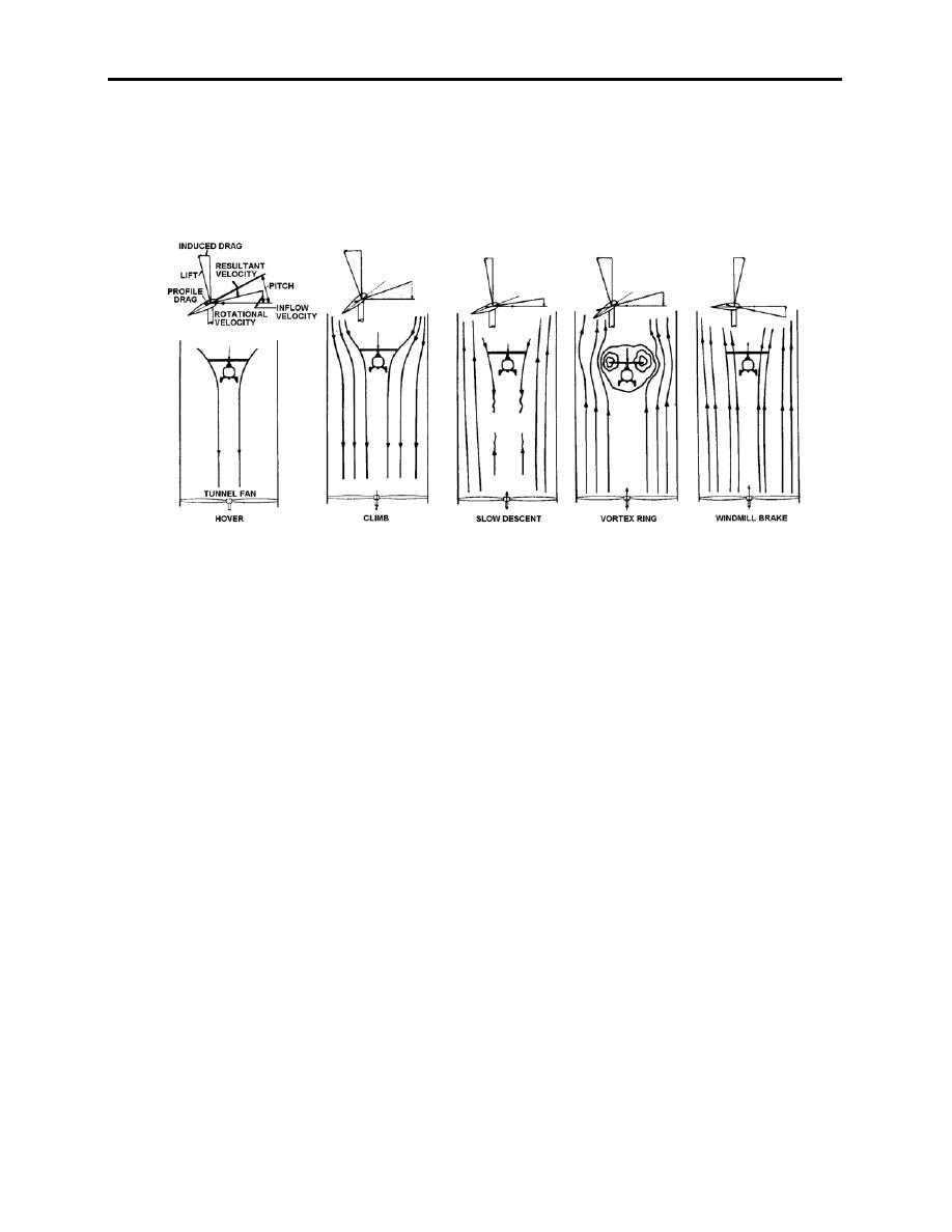
Figure 4-1
Beginning with the normal thrusting state, we will use an analogy of a tunnel fan (see figure
4-1). There are three possibilities of normal thrust -- hover, climb, and slow descent. For a
hover, envision the fan turned off with the rotor producing a downward flow. For a climb, think
of a fan pulling air down through the tunnel and rotor, increasing the induced flow through the
rotor. For a slow descent, reverse the direction of the fan to blow air up the tunnel, decreasing
the rotor downwash, but not enough to reverse the downwash near the rotor.
Now turn the speed of the fan enough to equalize the flow of air going up the tunnel with the
rotor induced downwash. At this point, rotor tip vortices are not allowed to move from the
vicinity of the rotor, enveloping the outer rim of the rotor in a bubble of air. Thrust developed by
the rotor becomes essentially negligible, and the helicopter descent rate increases dramatically.
This is known as vortex ring state. The onset of vortex ring state varies with types of helicopters
because the onset varies proportionally in regards to descent rate and hover induced velocity.
The helicopter enters this state at about induced velocity, peaks at induced velocity, and
becomes clear of this phenomenon at approximately 1 induced velocity. Flight path descent
profiles also determine the length of stay in this state, and there is evidence descent angles of 70
are worse than those of 90. Approach angles less than 50 combined with forward speeds of
15 - 30 kts allow enough new mass flow of air to blow the tip vortices behind the rotor system.
The TH-57 should avoid descent rates greater than 800 ft/min, less than 40 kts IAS, and descent
angles greater than 45.
As the fan is turned up to maximum, the net flow becomes upward through the rotor. The
rotor actually takes some energy from the passing wind and slows it down, but since rotor
systems can't store or dissipate energy like windmills generating electricity, the point is academic
4-2 AUTOROTATION
|
|
Privacy Statement - Press Release - Copyright Information. - Contact Us |
