 |
|||
|
|
|||
|
|
|||
| ||||||||||
|
|  HELICOPTER AERODYNAMICS WORKBOOK
CHAPTER 3
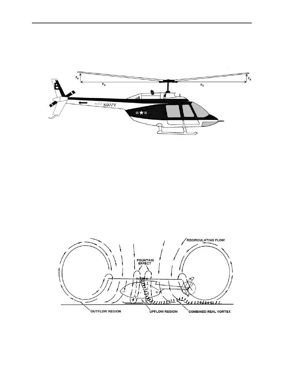
CONING
As the rotor blades turn, centrifugal force is created which pulls the blades outward from the
hub. When lift (or aerodynamic force) is created and combines with centrifugal force coning
occurs (see figure 3-11). Coning increases as lift increases.
Figure 3-11
VORTICES
As the rotor blades rotate and lift is produced, high pressure is formed below the blade and low
pressure above the blade. The sharp trailing edge of the blade keeps the high-pressure air from the
low-pressure area on most of the blade, except for the tip, where nothing prevents the air from
curling up from the bottom of the blade to the top. This air continues to spiral and drops off to
form the trailing tip vortex. This vortex continues to spin, and the velocity drops off with
increasing distance from the origin. In a hover, the vortices of one revolution impinge on the
vortices of the following revolutions, causing an uneven path of the vortices, which eventually
destroy each other. These tip vortices affect the induced velocity through the rotor system, and
due to this impingement and resultant unsteadiness in the flow field, a rotor system in a hover
creates its own gusty air, requiring the pilot to constantly correct to maintain a hover (figure 3-12).
Figure 3-12
HELICOPTER POWERED FLIGHT ANALYSIS 3-11
|
|
Privacy Statement - Press Release - Copyright Information. - Contact Us |
