 |
|||
|
|
|||
|
Page Title:
T-34C Wheel Brake System |
|
||
| ||||||||||
|
|  CHAPTER TWENTY THREE
T-34C AIRCRAFT SYSTEMS FAMILIARIZATION
WORKBOOK
2302. T-34C WHEEL BRAKE SYSTEM
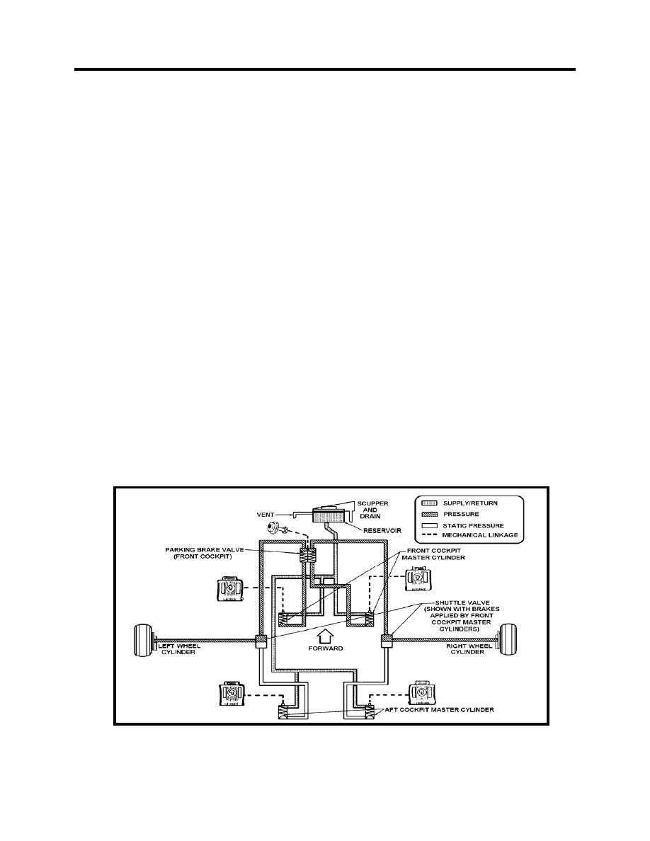
The main landing gear wheels are equipped with hydraulic brakes which stop and steer the
aircraft. The brakes are unboosted, hydraulic, single-disc and can be actuated on either or both
wheels. Forward toe pressure on the upper part of the rudder pedal(s) pressurizes the system
hydraulic fluid through the action of the master cylinder located on each rudder pedal. Shuttle
valves located between the front and aft master cylinders isolate the master cylinders not in use.
A brake assembly on each main mount wheel is made up of a rotating disc attached to the wheel,
and a nonrotating housing attached to the strut consisting of the wheel cylinder pistons and brake
pads (pucks). Minimum pad thickness on preflight inspection is 1/10 inch. The cockpit that first
applies the brakes has control; however, due to action of the shuttle valves, the pilot exerting the
greatest amount of toe pressure on the brakes can "take control" of the brakes. If both pilots push
with equal pressure, loss of braking may occur. The brakes do not have antilock devices. The
system is serviced through a filler neck located forward of the windshield.
Parking Brake
The parking brake system is comprised of the normal brake system plus a parking brake handle
and valve. A center lock button type parking brake handle is located in the front cockpit on the
right subpanel. The parking brakes can only be set by the pilot in the front cockpit by first
depressing the center lock button and pulling out the handle, then applying the toe brakes.
Pulling the handle out sets a one-way check valve and any pressure subsequently applied by the
front cockpit pedals to the brakes is held. Pushing the handle in unseats the check valve, thereby
releasing the pressure. The center button must be depressed prior to setting or releasing the
brake handle. Damage may occur if the parking brake is set when the brakes are overheated or
in freezing ambient temperatures.
Figure 23-1 Wheel Brake System
23-2
WHEEL BRAKE SYSTEM
|
|
Privacy Statement - Press Release - Copyright Information. - Contact Us |
