 |
|||
|
|
|||
|
|
|||
| ||||||||||
|
|  CHAPTER EIGHT
T-34C AIRCRAFT SYSTEMS FAMILIARIZATION
WORKBOOK
802.
POWER PLANT CONTROL SYSTEM
Power Plant Control Quadrant
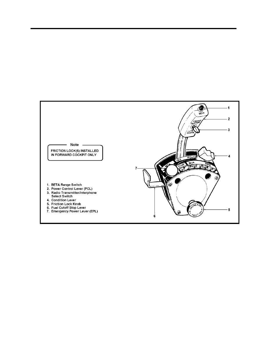
The power plant control quadrant, located on the left sidewall of each cockpit, provides control of
outboard PCL, the center condition lever, and the inboard EPL are partially enclosed within a
lock knob is located on the inside face of the front cockpit quadrant only. A fuel cutoff stop release
lever is located at the rear of both quadrants.
Figure 8-1 Power Plant Control Quadrant
Power Control Lever
The Power Control Lever (PCL) controls engine power output and propeller reverse thrust. The
PCL operates in two ranges: POWER and BETA. The PCL in the front cockpit is connected to
the cam box assembly located on the right side of the accessory gearbox. The cam box assembly
allows the PCL to operate the FCU in the POWER range and the beta valve in the BETA range.
In the POWER range, the PCL controls power from IDLE to MAX. Advancing the PCL
increases fuel flow and power output increases. Retarding the PCL decreases fuel flow and
power output decreases. Retarding the PCL aft to the IDLE position sets idle engine speed of
62-65% N1.
8-2 POWER PLANT CONTROL SYSTEM
|
|
Privacy Statement - Press Release - Copyright Information. - Contact Us |
