 |
|||
|
|
|||
|
|
|||
| ||||||||||
|
|  T-34C AIRCRAFT SYSTEMS FAMILIARIZATION
CHAPTER TEN
WORKBOOK
1002. ENGINE START SYSTEM
The engine start system provides engine rotation and ignition for engine start. A two-position
manual toggle switch labeled STARTER, ON, OFF is located on the starter/ignition control
panel, right-hand subpanel in each cockpit. Placing the switch to the ON position causes
operation of the igniters and engine starter, providing air and spark. The switch must be
manually turned OFF, otherwise the generator will not energize. Electrical command is not
required to activate either cockpit starter switch. Accidental selection of ON with the generator
running will disconnect the generator and cause the MASTER CAUTION and GENERATOR
lights to illuminate. The starter is a 28-VDC, 800-amp motor, located within the same housing
as the generator, but having a separate set of electrical windings. The starter provides initial
rotation of the compressor for engine start and is normally limited to 40 seconds use. Since the
starter develops damaging heat while rotating the compressor, the starter is limited to three 40-
second attempts with a 60-second cooling off period after the first two, and a 30-minute cooling
off period after the third attempt (40 seconds ON, 60 seconds OFF, 40 seconds ON, 60 seconds
OFF, 40 seconds ON, 30 minutes OFF).
1003. LIGHTS
Warning, Caution, and Advisory Lights
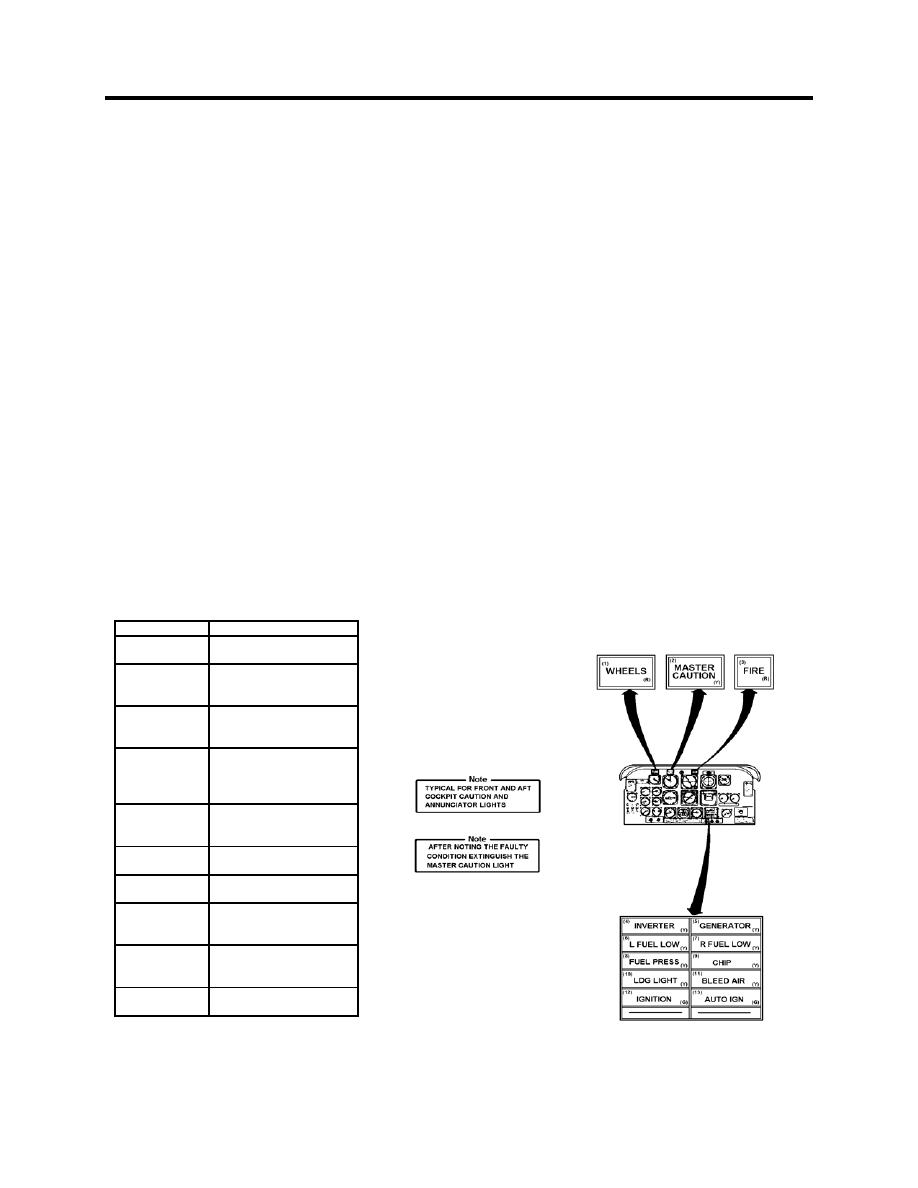
The warning, caution, and advisory lights provide a visual warning of malfunctions of aircraft
equipment, unsafe operating conditions, or notice that a particular system is in operation. A test
switch provides for a check of the light bulbs in each indicator. All lights are powered by 28 VDC.
LIGHT
MEANING
INVERTER
Loss of 115 AC or
26 VAC power.
Failure of the 115 VAC,
1-amp CB with Inverter
No. 1 selected
GENERATOR
Starter Switch ON, low
voltage output or
generator failure.
L FUEL LOW
Respective wing fuel
R FUEL LOW
quantity below
approximately 90 lbs.
usable.
FUEL PRESS
Low pressure output
from engine-driven fuel
boost pump.
CHIP
Metal particles present
in oil system.
LDG LIGHT
Gear retracted with one
or both LDG lights ON.
BLEED AIR
Cockpit heating (bleed)
air overtemperature
condition exists.
IGNITION
Engine igniters
energized by starter
switch or auto-ignition.
AUTO IGN
Autoignition switch ON,
system armed.
Figure 10-1 Warning/Caution/Annunciator Lights Fault Lights
ELECTRICAL SUBSYSTEMS
10-3
|
|
Privacy Statement - Press Release - Copyright Information. - Contact Us |