 |
|||
|
|
|||
|
|
|||
| ||||||||||
|
|  CHAPTER FIVE
AVIATION WEATHER
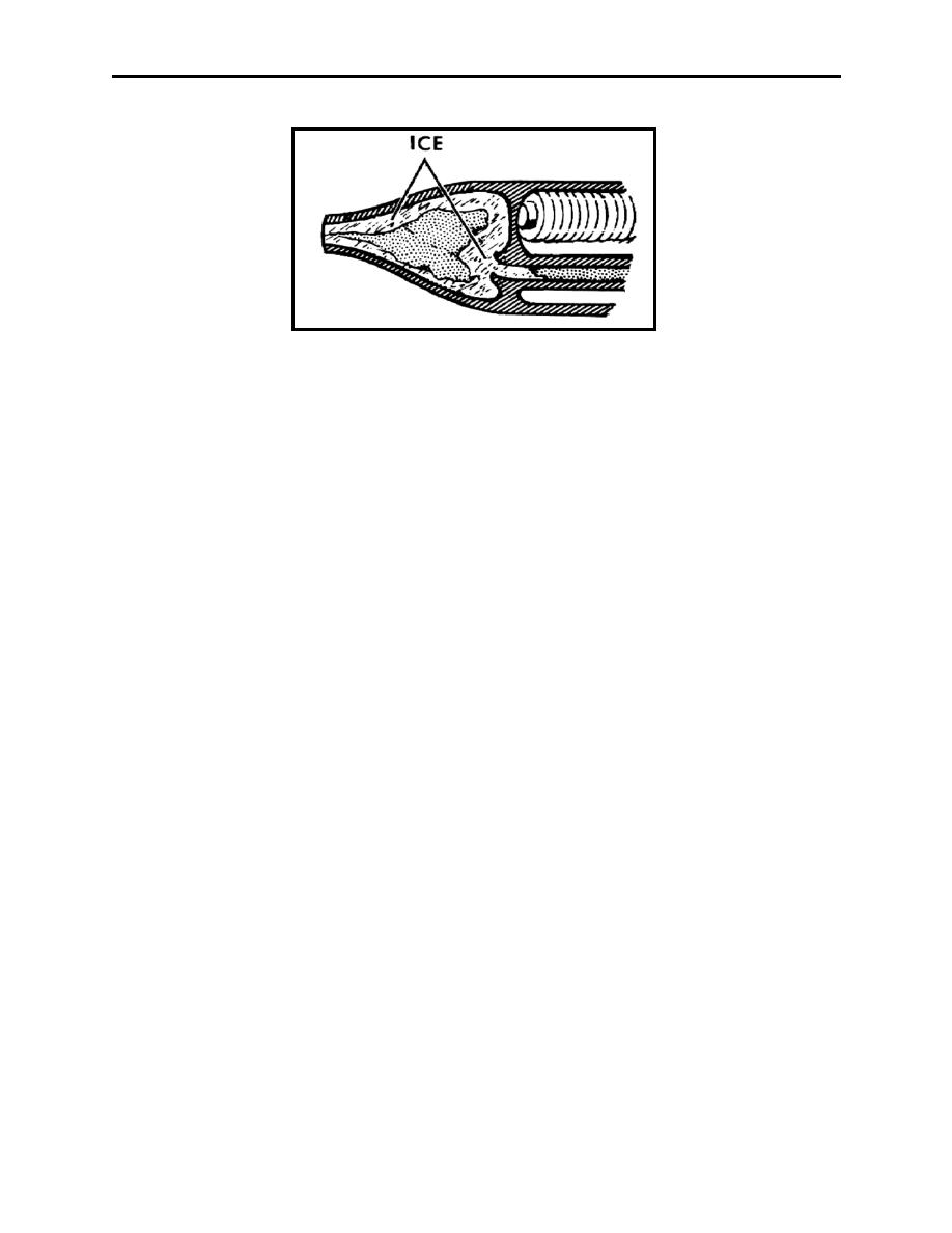
Figure 5-11 Pitot Tube Icing
During flight, it can be difficult to detect ice on areas such as the empennage that may be
impossible to see. Cues that signal the potential for icing include the following:
1.
Ice on windshield wiper arms or projections such as engine drain tubes, pitot tubes, engine
inlet lips, or propeller spinners,
2.
decreasing airspeed with constant power and altitude, and
3.
ice detector annunciation.
Icing on rotary wing aircraft is related to those involving wings and propellers. Ice formation on
the helicopter main rotor system or antitorque rotor system may produce serious vibration, loss
of efficiency or control, and can significantly deteriorate the available RPM to a level where safe
landing cannot be assured. In fact, a 3/16-inch (4.8-mm) coating of ice is sufficient to prevent
some helicopters from maintaining flight in a hover.
507.
OTHER TYPES OF AIRCRAFT ICING
Induction icing in flights through clouds containing super-cooled water droplets, air intake duct
icing is similar to wing icing. However, the ducts may ice when skies are clear and temperatures
are above freezing. The reduced pressure that exists at the intake lowers the temperature to the
point that condensation and/or deposition take place, resulting in the formation of ice. The
degree of temperature decrease varies considerably with different types of engines. However, if
the free air temperature is 10C or less (especially near the freezing point) and the relative
humidity is high, the possibility of induction icing exists. Ingestion of ice shed ahead of the
compressor inlet may cause severe foreign object damage to the engine.
Compressor icing ice forming on compressor inlet screens and compressor inlet guide vanes
will restrict the flow of inlet air, eventually causing engine flameout. The reduction in airflow is
noticeable through a loss of thrust and a rapid rise in exhaust gas temperature. As the airflow
decreases, the fuel-air ratio increases, which in turn raises the temperature of the gases going to
the turbine. The fuel control attempts to correct any loss in engine RPM by adding more fuel,
which merely aggravates the condition. Ice build-up on inlet screens sufficient to cause turbine
failure can occur in less than one minute under severe conditions.
5-16
Weather Hazards of Turbulence, Icing, Ceilings, Visibility, and Ash Clouds
|
|
Privacy Statement - Press Release - Copyright Information. - Contact Us |
